

AL-E048E UNIVERSAL LAB TRAINER (ULT)
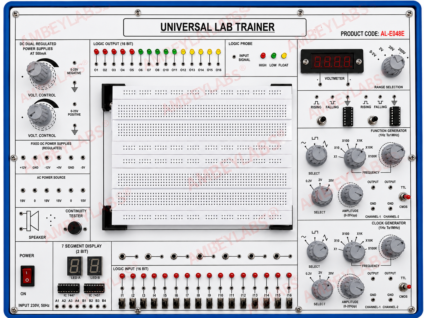
Project Information
- Category: ELECTRONICS ENGINEERING
- Sub Category: DIGITAL ELECTRONICS
- Model Number: AL-E048E
Description
AL-E048E UNIVERSAL
LAB TRAINER (ULT)
·
DETAILED
TECHNICAL SPECIFICATIONS
· Model: AL-E048E – UNIVERSAL LAB TRAINER
· UNIVERSAL LAB TRAINER
1. General
Description
AL-E048E Universal Lab Trainer is a comprehensive electronics and digital
laboratory training platform designed for practical experimentation in basic
electronics, digital electronics, logic circuits, waveform generation,
measurement, and microprocessor/microcontroller interfacing. The unit
integrates regulated DC supplies, AC source, logic inputs/outputs, function
generator, clock generator, digital voltmeter, logic probe, breadboard,
7-segment display and other commonly required laboratory facilities in a single
compact panel.
2. Technical
Specifications
|
·
Parameter |
·
Specification |
|
· Model |
· AL-E048E |
|
· Product Type |
· Universal Electronics / Digital Lab Trainer |
|
· Input Supply |
· 230 V AC, 50 Hz |
|
· Construction |
· Rugged, compact, bench-top trainer panel |
|
· Front Panel |
· Clearly marked and screen-printed technical
layout |
|
· Experiment Platform |
· Large solderless breadboard |
|
· DC Variable Supply |
· Dual regulated DC power supplies |
|
· Variable DC Output |
· 0–25 V DC, adjustable |
|
· DC Supply Current |
· Up to 500 mA |
|
· Polarity |
· Positive and negative adjustable outputs |
|
· Fixed DC Supplies |
· +12 V, −12 V, +5 V, −5 V and GND |
|
· AC Power Source |
· Multiple AC output terminals, including 19 V / 15
V selections as marked |
|
· Digital Voltmeter |
· Built-in digital display with selectable voltage
ranges |
|
· Logic Input |
· 16-bit logic input section |
|
· Logic Output |
· 16-bit LED logic output section |
|
· Logic Indicators |
· Red, green and yellow LED indication |
|
· Logic Probe |
· High / Low / Float logic indication |
|
· Function Generator |
· Built-in multi-waveform signal generator |
|
· Function Generator Frequency |
· Approx. 1 Hz to 1 MHz* |
|
· Waveforms |
· Sine / square / triangular or selectable
waveforms as provided |
|
· Amplitude Control |
· Adjustable amplitude, approximately 0–20 Vpp* |
|
· Frequency Selection |
· Multi-range frequency multiplier selection |
|
· Clock Generator |
· Built-in variable-frequency clock generator |
|
· Clock Frequency |
· Approx. 1 Hz to 1 MHz* |
|
· Clock Outputs |
· Dual channel outputs |
|
· TTL / CMOS |
· Dedicated TTL/CMOS output facility |
|
· 7-Segment Display |
· Dual 7-segment LED display |
|
· Display Driver ICs |
· IC 7447 / IC 7457 positions provided on panel |
|
· Continuity Tester |
· Built-in continuity testing facility |
|
· Audio Facility |
· Built-in speaker |
|
· Breadboard |
· Large solderless, reusable experimental
breadboard |
|
· Connection Terminals |
· 4 mm / laboratory connection terminals as
provided |
|
· Power ON/OFF |
· Illuminated/rocker type mains switch |
|
· Protection |
· Fused/protected laboratory power input
arrangement |
|
· Mounting |
· Suitable for laboratory bench-top operation |
· *Frequency and amplitude ranges should be treated
as nominal/as-marked on the supplied unit; final procurement
specifications can be confirmed against the manufacturer's test
certificate/datasheet.
3. Built-in
DC Power Supply
· The trainer incorporates a dual regulated
variable DC power supply suitable for powering electronic circuits during
experiments.
· Two independently adjustable voltage controls.
· Approx. 0–25 V DC variable range.
· Output current capability up to 500 mA.
· Positive and negative output facility.
· Dedicated ground terminals.
· Suitable for analog and digital circuit
experiments.
Fixed
Regulated Outputs
· The panel provides permanently available regulated
outputs:
· +12 V DC
· −12 V DC
· +5 V DC
· −5 V DC
· GND
4. Logic
Input Section
· A 16-bit digital logic input section is
provided for testing combinational and sequential digital circuits.
· 16 individual logic channels.
· Individual switches for logic-state selection.
· Corresponding LED status indication.
· Clearly identified input channels.
· Suitable for HIGH/LOW logic experiments.
· Direct connection to the breadboard through
laboratory terminals.
5. Logic
Output Section
· The trainer provides a 16-bit logic output
indication system.
· 16 independent logic output channels.
· Individual LED indicators.
· Red/green/yellow visual indication.
· Channel identification from O1 to O16.
· Useful for observing the output state of digital
circuits.
· Suitable for logic gates, counters, registers,
multiplexers and other digital experiments.
6. Logic
Probe
· Built-in logic probe facility enables quick
checking of digital signal conditions.
Indications:
· HIGH
· LOW
· FLOAT / undefined state
· The probe is useful for troubleshooting and
verifying digital circuit operation without requiring an external logic
analyzer.
7. Function
Generator
· An integrated function generator is provided for
supplying test signals to experimental circuits.
Features
· Multiple selectable waveforms.
· Frequency selection through multiple ranges.
· Fine frequency adjustment.
· Variable amplitude control.
· Dedicated output terminals.
· TTL/CMOS-compatible output facility.
· Suitable for analog and digital laboratory
experiments.
· Nominal frequency range: approximately 1 Hz to 1 MHz, according to
the panel marking.
8. Clock
Generator
· A separate clock generator is incorporated for
digital circuit applications.
Features
· Variable clock frequency.
· Multiple frequency ranges.
· Frequency multiplier/range selection.
· Adjustable amplitude.
· Dual channel output arrangement.
· TTL/CMOS-compatible output.
· Dedicated GND terminals.
· This facility is particularly useful for:
· Flip-flops
· Counters
· Shift registers
· Frequency dividers
· Digital timing circuits
· Sequential logic experiments
9. Digital
Voltmeter
· A built-in digital voltmeter is provided for
convenient measurement of circuit voltage.
· Bright digital display.
· Selectable measurement range.
· Dedicated positive and negative measurement
terminals.
· Suitable for DC voltage measurements during
experiments.
· Panel-mounted construction.
10.
7-Segment Display Section
· The trainer includes a dual 7-segment display
section for digital display experiments.
Facilities
· Two 7-segment LED displays.
· Individual segment access.
· A/B display identification.
· Provision for associated driver ICs.
· Suitable for:
· Decimal display experiments
· BCD-to-7-segment conversion
· Counter circuits
· Decoder experiments
· Digital display interfacing
11.
Solderless Breadboard
· A large integrated solderless breadboard provides
the main experimental work area.
· Large working area.
· Reusable interconnection system.
· No soldering required.
· Suitable for ICs, resistors, capacitors, diodes,
transistors and jumper wires.
· Easy circuit modification and troubleshooting.
· Direct access to trainer power and signal sources.
12. AC Power
Source
· The trainer provides multiple AC source terminals
for laboratory experiments.
· Panel-marked outputs include 19 V and 15 V AC
selections, along with common/reference terminals.
· The AC source can be used for experiments
involving:
· Rectifiers
· Filters
· Diode circuits
· AC measurement
· Transformer-related demonstrations
· Basic power electronics experiments
13.
Continuity Tester
· An integrated continuity tester is provided for
checking electrical connections.
· Quick continuity verification.
· Audio indication through built-in speaker.
· Useful for checking wires, switches and circuit
connections.
· Helps in troubleshooting experimental circuits.
14. Speaker
/ Audio Output
· A built-in speaker is provided for audible
indication and basic audio experiments.
· It can be used with:
· Continuity tester
· Oscillator circuits
· Tone generator circuits
· Audio-frequency experiments
· Digital buzzer/output demonstrations
15. Typical
Experiments Supported
The AL-E048E Universal Lab Trainer can be
used for a wide range of laboratory experiments, including:
Basic
Electronics
· Verification of Ohm's Law
· Series and parallel circuits
· Voltage and current measurement
· Diode characteristics
· Rectifier circuits
· Zener diode characteristics
· Transistor characteristics
· Transistor switching
Digital
Electronics
· Verification of basic logic gates
· Universal gates – NAND and NOR
· XOR/XNOR experiments
· Half and full adders
· Multiplexer and demultiplexer
· Encoder and decoder
· Flip-flops
· Counters
· Shift registers
· Frequency divider circuits
· BCD and 7-segment display
· Digital comparator circuits
Signal
Generation & Measurement
· Sine-wave generation
· Square-wave generation
· Triangular-wave generation
· Frequency measurement
· Amplitude measurement
· Clock signal generation
· TTL/CMOS signal experiments
16.
Mechanical & Construction Features
· Rugged laboratory-grade enclosure.
· Attractive blue-and-white front-panel
finish.
· Clearly engraved/screen-printed labels.
· All major controls conveniently accessible from the
front.
· Panel-mounted knobs, switches, LEDs and terminals.
· Integrated breadboard for rapid circuit assembly.
· Suitable for educational institutions, engineering
colleges, polytechnics and electronics laboratories.
· Designed for repeated student laboratory use.
17. Standard
Accessories
· The trainer may be supplied with:
· Patch cords / connecting leads
· Jumper wires
· IC connection accessories
· Breadboard jumper set
· Power cord
· User/working manual
· Instruction documentation
18.
Recommended Application Areas
· Engineering Colleges | Polytechnic Institutes | ITI
| Industrial Training Centres | Electronics Laboratories | Digital Electronics
Laboratories | Communication Laboratories | R&D Training Centers
Technical Details
AL-E048E UNIVERSAL LAB TRAINER (ULT)
· DETAILED TECHNICAL SPECIFICATIONS
· Model: AL-E048E – UNIVERSAL LAB TRAINER
· UNIVERSAL LAB TRAINER
1. General Description
AL-E048E Universal Lab Trainer is a comprehensive electronics and digital laboratory training platform designed for practical experimentation in basic electronics, digital electronics, logic circuits, waveform generation, measurement, and microprocessor/microcontroller interfacing. The unit integrates regulated DC supplies, AC source, logic inputs/outputs, function generator, clock generator, digital voltmeter, logic probe, breadboard, 7-segment display and other commonly required laboratory facilities in a single compact panel.
2. Technical Specifications
· Parameter | · Specification |
· Model | · AL-E048E |
· Product Type | · Universal Electronics / Digital Lab Trainer |
· Input Supply | · 230 V AC, 50 Hz |
· Construction | · Rugged, compact, bench-top trainer panel |
· Front Panel | · Clearly marked and screen-printed technical layout |
· Experiment Platform | · Large solderless breadboard |
· DC Variable Supply | · Dual regulated DC power supplies |
· Variable DC Output | · 0–25 V DC, adjustable |
· DC Supply Current | · Up to 500 mA |
· Polarity | · Positive and negative adjustable outputs |
· Fixed DC Supplies | · +12 V, −12 V, +5 V, −5 V and GND |
· AC Power Source | · Multiple AC output terminals, including 19 V / 15 V selections as marked |
· Digital Voltmeter | · Built-in digital display with selectable voltage ranges |
· Logic Input | · 16-bit logic input section |
· Logic Output | · 16-bit LED logic output section |
· Logic Indicators | · Red, green and yellow LED indication |
· Logic Probe | · High / Low / Float logic indication |
· Function Generator | · Built-in multi-waveform signal generator |
· Function Generator Frequency | · Approx. 1 Hz to 1 MHz* |
· Waveforms | · Sine / square / triangular or selectable waveforms as provided |
· Amplitude Control | · Adjustable amplitude, approximately 0–20 Vpp* |
· Frequency Selection | · Multi-range frequency multiplier selection |
· Clock Generator | · Built-in variable-frequency clock generator |
· Clock Frequency | · Approx. 1 Hz to 1 MHz* |
· Clock Outputs | · Dual channel outputs |
· TTL / CMOS | · Dedicated TTL/CMOS output facility |
· 7-Segment Display | · Dual 7-segment LED display |
· Display Driver ICs | · IC 7447 / IC 7457 positions provided on panel |
· Continuity Tester | · Built-in continuity testing facility |
· Audio Facility | · Built-in speaker |
· Breadboard | · Large solderless, reusable experimental breadboard |
· Connection Terminals | · 4 mm / laboratory connection terminals as provided |
· Power ON/OFF | · Illuminated/rocker type mains switch |
· Protection | · Fused/protected laboratory power input arrangement |
· Mounting | · Suitable for laboratory bench-top operation |
· *Frequency and amplitude ranges should be treated as nominal/as-marked on the supplied unit; final procurement specifications can be confirmed against the manufacturer's test certificate/datasheet.
3. Built-in DC Power Supply
· The trainer incorporates a dual regulated variable DC power supply suitable for powering electronic circuits during experiments.
· Two independently adjustable voltage controls.
· Approx. 0–25 V DC variable range.
· Output current capability up to 500 mA.
· Positive and negative output facility.
· Dedicated ground terminals.
· Suitable for analog and digital circuit experiments.
Fixed Regulated Outputs
· The panel provides permanently available regulated outputs:
· +12 V DC
· −12 V DC
· +5 V DC
· −5 V DC
· GND
4. Logic Input Section
· A 16-bit digital logic input section is provided for testing combinational and sequential digital circuits.
· 16 individual logic channels.
· Individual switches for logic-state selection.
· Corresponding LED status indication.
· Clearly identified input channels.
· Suitable for HIGH/LOW logic experiments.
· Direct connection to the breadboard through laboratory terminals.
5. Logic Output Section
· The trainer provides a 16-bit logic output indication system.
· 16 independent logic output channels.
· Individual LED indicators.
· Red/green/yellow visual indication.
· Channel identification from O1 to O16.
· Useful for observing the output state of digital circuits.
· Suitable for logic gates, counters, registers, multiplexers and other digital experiments.
6. Logic Probe
· Built-in logic probe facility enables quick checking of digital signal conditions.
Indications:
· HIGH
· LOW
· FLOAT / undefined state
· The probe is useful for troubleshooting and verifying digital circuit operation without requiring an external logic analyzer.
7. Function Generator
· An integrated function generator is provided for supplying test signals to experimental circuits.
Features
· Multiple selectable waveforms.
· Frequency selection through multiple ranges.
· Fine frequency adjustment.
· Variable amplitude control.
· Dedicated output terminals.
· TTL/CMOS-compatible output facility.
· Suitable for analog and digital laboratory experiments.
· Nominal frequency range: approximately 1 Hz to 1 MHz, according to the panel marking.
8. Clock Generator
· A separate clock generator is incorporated for digital circuit applications.
Features
· Variable clock frequency.
· Multiple frequency ranges.
· Frequency multiplier/range selection.
· Adjustable amplitude.
· Dual channel output arrangement.
· TTL/CMOS-compatible output.
· Dedicated GND terminals.
· This facility is particularly useful for:
· Flip-flops
· Counters
· Shift registers
· Frequency dividers
· Digital timing circuits
· Sequential logic experiments
9. Digital Voltmeter
· A built-in digital voltmeter is provided for convenient measurement of circuit voltage.
· Bright digital display.
· Selectable measurement range.
· Dedicated positive and negative measurement terminals.
· Suitable for DC voltage measurements during experiments.
· Panel-mounted construction.
10. 7-Segment Display Section
· The trainer includes a dual 7-segment display section for digital display experiments.
Facilities
· Two 7-segment LED displays.
· Individual segment access.
· A/B display identification.
· Provision for associated driver ICs.
· Suitable for:
· Decimal display experiments
· BCD-to-7-segment conversion
· Counter circuits
· Decoder experiments
· Digital display interfacing
11. Solderless Breadboard
· A large integrated solderless breadboard provides the main experimental work area.
· Large working area.
· Reusable interconnection system.
· No soldering required.
· Suitable for ICs, resistors, capacitors, diodes, transistors and jumper wires.
· Easy circuit modification and troubleshooting.
· Direct access to trainer power and signal sources.
12. AC Power Source
· The trainer provides multiple AC source terminals for laboratory experiments.
· Panel-marked outputs include 19 V and 15 V AC selections, along with common/reference terminals.
· The AC source can be used for experiments involving:
· Rectifiers
· Filters
· Diode circuits
· AC measurement
· Transformer-related demonstrations
· Basic power electronics experiments
13. Continuity Tester
· An integrated continuity tester is provided for checking electrical connections.
· Quick continuity verification.
· Audio indication through built-in speaker.
· Useful for checking wires, switches and circuit connections.
· Helps in troubleshooting experimental circuits.
14. Speaker / Audio Output
· A built-in speaker is provided for audible indication and basic audio experiments.
· It can be used with:
· Continuity tester
· Oscillator circuits
· Tone generator circuits
· Audio-frequency experiments
· Digital buzzer/output demonstrations
15. Typical Experiments Supported
The AL-E048E Universal Lab Trainer can be used for a wide range of laboratory experiments, including:
Basic Electronics
· Verification of Ohm's Law
· Series and parallel circuits
· Voltage and current measurement
· Diode characteristics
· Rectifier circuits
· Zener diode characteristics
· Transistor characteristics
· Transistor switching
Digital Electronics
· Verification of basic logic gates
· Universal gates – NAND and NOR
· XOR/XNOR experiments
· Half and full adders
· Multiplexer and demultiplexer
· Encoder and decoder
· Flip-flops
· Counters
· Shift registers
· Frequency divider circuits
· BCD and 7-segment display
· Digital comparator circuits
Signal Generation & Measurement
· Sine-wave generation
· Square-wave generation
· Triangular-wave generation
· Frequency measurement
· Amplitude measurement
· Clock signal generation
· TTL/CMOS signal experiments
16. Mechanical & Construction Features
· Rugged laboratory-grade enclosure.
· Attractive blue-and-white front-panel finish.
· Clearly engraved/screen-printed labels.
· All major controls conveniently accessible from the front.
· Panel-mounted knobs, switches, LEDs and terminals.
· Integrated breadboard for rapid circuit assembly.
· Suitable for educational institutions, engineering colleges, polytechnics and electronics laboratories.
· Designed for repeated student laboratory use.
17. Standard Accessories
· The trainer may be supplied with:
· Patch cords / connecting leads
· Jumper wires
· IC connection accessories
· Breadboard jumper set
· Power cord
· User/working manual
· Instruction documentation
18. Recommended Application Areas
· Engineering Colleges | Polytechnic Institutes | ITI | Industrial Training Centres | Electronics Laboratories | Digital Electronics Laboratories | Communication Laboratories | R&D Training Centers