

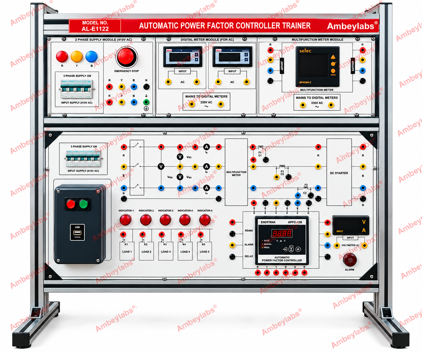
AL-E1122 AUTOMATIC POWER FACTOR CONTROLLER TRAINER
Project Information
- Category: ELECTRICAL ENGINEERING
- Sub Category: ELECTRICAL ENGINEERING
- Model Number: AL-E1122
Description
AL-E1122
AUTOMATIC POWER FACTOR CONTROLLER
TRAINER
Automatic Power
Factor Controller Trainer
Model AL-E11221
-----------------------------------------------------------------------------------------------------------------------------------------------------------
General Description
The Automatic Power
Factor Controller Trainer, Model AL-E1122, is designed for practical study of
power factor measurement, automatic power factor correction, three-phase
electrical supply systems, and capacitor bank switching. The trainer is built
on an aluminium-profile frame with clearly labelled modules, electrical
connection terminals, measuring instruments, control switches, indicator lamps,
and an automatic power factor controller.
It is suitable for
electrical engineering laboratories, polytechnic institutions, industrial
training centres, and power systems laboratories.
2. Detailed Technical Specifications
|
S. No. |
Parameter |
Technical
specification |
|
1 |
Equipment name |
Automatic Power
Factor Controller Trainer |
|
2 |
Model number |
AL-E1122 |
|
3 |
Equipment type |
Electrical
engineering training system |
|
4 |
Frame construction |
Aluminium-profile
structure |
|
5 |
Panel construction |
Modular front panel
with printed circuit diagrams and labels |
|
6 |
Three-phase supply
module |
Three-phase supply
section with R, Y and B phase indication |
|
7 |
Supply input |
Three-phase AC
supply; exact rating to be confirmed |
|
8 |
Main protection |
Circuit breaker
arrangement |
|
9 |
Emergency stop |
Dedicated
emergency-stop push button |
|
10 |
Digital meter
module |
Digital measuring
instruments for AC measurements |
|
11 |
Multifunction meter |
Multifunction electrical
measuring meter |
|
12 |
Measurement
terminals |
Colour-coded
terminals for electrical connections |
|
13 |
Circuit
demonstration panel |
Printed electrical
schematic and connection points |
|
14 |
Indicator lamps |
Multiple indicator
lamps for circuit status and demonstration |
|
15 |
Load switching |
Multiple
load-switching sections with labelled terminals |
|
16 |
Automatic
controller |
Automatic power
factor controller |
|
17 |
Controller
interface |
RS485 communication
terminals indicated on the panel |
|
18 |
Manual/automatic
operation |
Controller
operating modes as supported by the installed controller |
|
19 |
Voltage measurement |
Dedicated voltmeter
section |
|
20 |
Alarm facility |
Alarm indicator and
associated connection points |
|
21 |
USB interface |
USB connection
provided on the front panel |
|
22 |
Connection system |
Colour-coded
electrical terminals for practical experiments |
|
23 |
Intended
application |
Power factor
correction and power systems training |
The specifications
above distinguish features visible on the supplied trainer image from ratings
that require confirmation. Exact supply voltage, current, capacitor-bank
ratings and meter accuracy are not readable or confirmed.
3. Main Functional Modules
3.1 Three-Phase Supply Module
- Three-phase
supply section with R, Y and B phase indicators.
- Input supply
switching and circuit protection.
- Emergency-stop
facility.
- Colour-coded
terminals for phase and neutral connections.
3.2 Digital Meter Module
- Digital AC measurement
instruments.
- Dedicated input
terminals for measurement connections.
- Separate meter
supply connections, as indicated on the panel.
3.3 Multifunction Meter
Module
- Multifunction
electrical meter for monitoring supported electrical parameters.
- Colour-coded
input and output terminals.
- Front-panel
display and operating controls.
3.4 Automatic Power Factor Controller
- Automatic power
factor controller mounted on the front panel.
- Controller
connections for measurement and control signals.
- RS485, alarm and
relay connection terminals.
- Front-panel
controls and digital display.
3.5 Load Switching and Demonstration Module
- Multiple
labelled load sections.
- Indicator lamps
and switching terminals.
- Printed circuit
diagrams for practical circuit connection.
- Terminals for
studying switching and control operation.
3.6 Protection and Indication Module
- Emergency-stop
push button.
- Circuit breaker
arrangement.
- Phase-indication
lamps.
- Alarm indicator
and associated terminals.
4. Scope of Learning and Experiments
The trainer can be
used to conduct practical exercises related to its installed modules,
including:
- Study of a
three-phase AC supply system.
- Measurement of
AC electrical parameters using digital meters.
- Study of power
factor and its significance in AC circuits.
- Study of the
operating principle of an automatic power factor controller.
- Demonstration of
automatic and manual controller modes, where supported.
- Study of load
switching and its effect on electrical parameters.
- Observation of
power factor correction using suitable capacitive loads, if the
corresponding capacitor bank is included.
- Study of
controller alarm, relay and RS485 interfaces.
These experiments
should be matched to the actual supplied circuit configuration and controller
manual.
5. Construction and Safety Features
- Rigid
aluminium-profile supporting frame.
- Modular front
panel with printed labels and schematic diagrams.
- Colour-coded
electrical connection terminals.
- Main supply
protection through a circuit breaker.
- Emergency-stop
facility.
- Indicator lamps
for operational status.
- Clearly
identified measurement and controller connections.
The trainer must be
operated under qualified supervision. Appropriate earthing, overcurrent
protection and safe isolation should be verified before energising the equipment.
6. Standard Supply and Accessories
The following are
visible or indicated in the supplied image:
- Automatic Power
Factor Controller Trainer, Model AL-E1122.
- Integrated
three-phase supply and protection section.
- Digital AC meter
module.
- Multifunction meter.
- Automatic power
factor controller.
- Load-switching
and indicator modules.
- Front-panel
connection terminals.
The availability of
connecting leads, capacitor banks, external loads, manuals and software should
be confirmed with the supplier.
SCOPE OF
SUPPLY:
· Induction
Motor APFC Control Panel
· AC
Ind. Motor 1HP Mounted on Loading Arrangement
|
|
AL-E407E THREE PHASE INDUCTION MOTOR MOTOR SPECIFICATIONS: · AC
Squirrel Cage Induction Motor 3HP · Operating
Voltage:415V · Type:
AC · RPM:
1440 RPM. · Wattage:
2.2KW · Terminations:
6 BTI 15 Terminals · Shaft:
Single · Frame:132 · B3 · SPDP · 1P23 · 1C01 · Solid
Yoke Extension · Fitted
on Metal Base with Loading Arrangement |