

AL-E280 SINGLE PHASE CAPACITOR START INDUCTION MOTOR (CUT SECTION MOTOR)
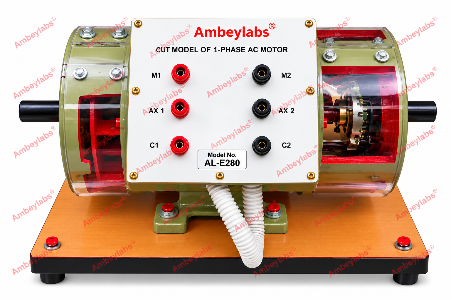
Project Information
- Category: ELECTRICAL ENGINEERING
- Sub Category: CUT SECTION MOTORS
- Model Number: AL-E280
Description
AL-E280
SINGLE PHASE CAPACITOR START INDUCTION MOTOR
(CUT
SECTION MOTOR)
MODEL NO: AL-E280
Detailed Technical Specifications
-----------------------------------------------------------------------------------------------------------------------------------------------------------------Product
Code: AL-E280 Product Name: Single Phase Capacitor Start Induction Motor (Cut
Section Motor) Application: Electrical Machines Laboratory, Electrical
Engineering Training, and Demonstration of Single-Phase Induction Motor
Construction and Working Principles.
1.
Motor Specifications
|
S. No. |
Parameter |
Technical Specification |
|
1 |
Type of Motor |
Single-Phase AC Capacitor Start
Induction Motor |
|
2 |
Model Number |
AL-E280 |
|
3 |
Rated Power |
1 HP (0.75 kW) |
|
4 |
Operating Voltage |
230 V AC, single-phase |
|
5 |
Rated Speed |
1440 RPM |
|
6 |
Starting Method |
Capacitor Start |
|
7 |
Motor Frame Size |
132 |
|
8 |
Shaft Arrangement |
Single Shaft |
|
9 |
Terminal Connections |
4 BTI 15 terminals, as specified |
|
10 |
Stator Construction |
Laminated steel core with main and
auxiliary windings |
|
11 |
Rotor Type |
Squirrel Cage Rotor |
|
12 |
Starting Component |
Starting capacitor and associated
switching arrangement |
|
13 |
Yoke |
Solid yoke extension |
|
14 |
Mounting Arrangement |
B3 – Foot-Mounted |
|
15 |
Enclosure Designation |
SPDP, as specified |
|
16 |
Protection Rating |
IP23, subject to manufacturer
confirmation |
|
17 |
Cooling Designation |
IC01, as specified |
|
18 |
Cut Section |
Selected sections exposed to
demonstrate internal construction |
|
19 |
Mounting Base |
Rigid metal base |
|
20 |
Intended Use |
Educational demonstration and
laboratory study |
2.
Constructional Features
- Stator assembly: Laminated magnetic core containing the main
winding and auxiliary starting winding.
- Squirrel cage rotor: Demonstrates the rotor construction and
electromagnetic torque-generation principle.
- Capacitor-start arrangement: Includes a starting capacitor and the
associated starting circuit, subject to the actual motor design.
- Cutaway housing: Exposes internal components for visual
identification and instructional demonstrations.
- Single shaft: Provides a visible mechanical output shaft.
- Solid yoke extension: Provides the specified structural extension.
- Four-terminal arrangement: Facilitates instructional study of the
motor's electrical connections.
- Metal base: Provides stable support for laboratory use.
3.
Experiments and Learning Objectives
The AL-E280 can be used for the
following educational activities:
- Study of single-phase capacitor-start induction motor
construction.
- Identification of stator, rotor, main winding, and auxiliary
winding.
- Study of the function of the starting capacitor.
- Understanding the starting torque mechanism in single-phase
induction motors.
- Study of the starting winding and main winding connections.
- Observation of the squirrel cage rotor and shaft arrangement.
- Understanding the operating principle of single-phase induction
motors.
- Study of motor terminal identification and connection procedures.
4.
Working Principle
A single-phase AC supply produces a
pulsating magnetic field, which by itself does not provide sufficient starting
torque in a conventional single-phase induction motor. The capacitor-start
arrangement introduces a phase difference between the currents in the main and
auxiliary windings, producing an approximate rotating magnetic field during
starting.
This generates starting torque and
initiates rotor rotation. In a conventional capacitor-start motor, a
centrifugal switch or another starting mechanism disconnects the auxiliary
winding and starting capacitor after the motor accelerates.
5.
General Requirements
- Suitable for electrical machines laboratories, polytechnics,
engineering colleges, and technical training institutes.
- Robust construction suitable for repeated laboratory
demonstrations.
- Internal components clearly visible through the cutaway sections.
- Main and auxiliary windings identifiable for instructional
purposes.
- Secure mounting on a rigid metal base.
- Clearly identified electrical terminals.
- Safe operation using the specified supply voltage and appropriate electrical
protection.
Specification verification note: The
designations SPDP, 1P23, and 1C01 have been retained or interpreted as
supplied; confirm the exact enclosure, protection, and cooling classifications
with the manufacturer before tender submission. Also verify the four-terminal
arrangement and starting-capacitor configuration against the actual motor
design.