

AL-E290A – 3-PHASE PERCENTAGE BIASED DIFFERENTIAL PROTECTION RELAY TRAINER
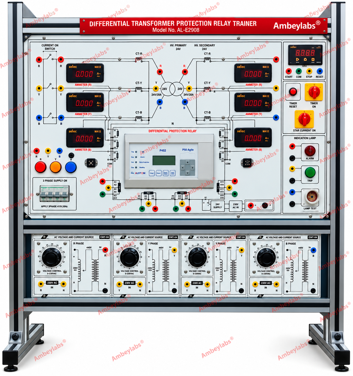
Project Information
- Category: ELECTRICAL ENGINEERING
- Sub Category: POWER SYSTEM AND PROTECTION LAB
- Model Number: AL-E290A
Description
AL-E290A 3PHASE PERCENTAGE
BIASED DIFFERENTIAL PROTECTION RELAY TRAINER
1. General Description
The AL-E290A 3-Phase Percentage Biased Differential Protection Relay
Trainer is a comprehensive laboratory training system designed for the
practical study of three-phase transformer differential protection using
the Merz-Price circulating-current principle.
The trainer enables students to understand percentage-biased
differential relay operation, current-transformer connections, relay pickup
characteristics, internal and external fault discrimination, transformer
protection, and numerical relay configuration through a PC interface.
The system is supplied as a modular laboratory trainer with protected
power-supply sections, current transformers, numerical differential relay,
digital measurement instruments, fault/trip indication and suitable safety
terminals.
2. Scope of Experiments
The trainer shall facilitate the following experiments:
1.Study of the operating principle of percentage-biased
differential protection.
2.Study of Merz-Price differential protection of
a three-phase transformer.
3.Plotting of the percentage-biased differential relay
characteristics.
4.Determination of the relay pickup current.
5.Determination of the operating current of the
differential relay.
6.Study of percentage bias and its effect on relay
operation.
7.Verification of different relay bias settings.
8.Testing at 15%, 30% and 45% bias settings.
9.Simulation and study of in-zone/internal
transformer faults.
10. Verification of relay
operation and tripping for internal faults.
11. Simulation and study
of out-of-zone/external faults.
12. Verification of
non-tripping for external faults.
13. Study of circulating
current under normal operating conditions.
14. Study of differential
current under fault conditions.
15. Study of
current-transformer operation in differential protection.
16. Measurement of phase
currents using digital ammeters.
17. Study of relay trip
indication.
18. Study of numerical
relay parameters and settings.
19. PC communication with
the numerical differential relay.
20. Relay parameter
setting through supplied software.
3. SYSTEM CONFIGURATION
The complete training system shall comprise:
|
S. No. |
Module |
Specification |
|
1 |
Three-Phase Power Supply |
415 V AC, 3-phase, 50 Hz |
|
2 |
Current Source |
440 V / 24 V / 20 A, 3 Nos. |
|
3 |
Auxiliary DC Supply |
+24 V DC, 10 A |
|
4 |
Digital AC Ammeter |
6 Nos. |
|
5 |
Digital Timer |
1 No. |
|
6 |
Current Transformer |
3 Nos. |
|
7 |
Numerical Differential Relay |
3-phase percentage-biased type |
|
8 |
Relay Current Rating |
1 A |
|
9 |
Bias Settings |
15%, 30%, 45% |
|
10 |
Relay Auxiliary Supply |
110 V DC |
|
11 |
Communication |
RS-232 |
|
12 |
PC Interface |
RS-232 to USB converter |
|
13 |
Relay Software |
Supplied |
|
14 |
Trip Indication |
Lamps / indicators / buzzer |
|
15 |
Emergency Stop |
Provided |
|
16 |
Short-Circuit Protection |
MCB |
|
17 |
Connection Terminals |
4 mm safety sockets |
|
18 |
Construction |
Modular aluminium-profile/rack-type cabinet |
|
19 |
Approx. Size |
42" × 24" |
4. THREE-PHASE POWER SUPPLY MODULE
The trainer shall incorporate an integrated three-phase power-supply
section.
Specifications
· Input voltage: 415
V AC
· Number of phases: 3
· Frequency: 50 Hz
· Supply tolerance: ±10%
· Phase identification:
R-Y-B
· MCB protection
provided.
· Emergency Stop
facility provided.
· Individual phase
indication provided.
· Clearly labelled
input and output terminals.
· Suitable protection
against short circuit and abnormal operating conditions.
Protection
· Three/four-pole MCB
as appropriate to the system configuration.
· Emergency isolation
through emergency-stop switch.
· Proper earthing
provision.
· Protected front-panel
connection points.
5. THREE-PHASE CURRENT SOURCE MODULE
A dedicated current-source section shall be provided for testing the
differential protection relay.
Specifications
· Current-source arrangement:
3 Nos.
· Source specification:
440 V / 24 V / 20 A
· Three-phase
operation.
· Controlled current
injection facility.
· Suitable for
differential relay characteristic testing.
· Suitable for
pickup-current testing.
· Suitable for internal
and external fault simulation.
· Output available
through safety terminals.
· Current
adjustment/control shall be provided as required for laboratory testing.
The current source shall permit controlled variation of test current for
obtaining relay operating and restraining characteristics.
6. CURRENT TRANSFORMER MODULE
The trainer shall include three current transformers for three-phase
differential protection experiments.
Specifications
· Number of CTs: 3
Nos.
· Application:
Differential protection
· Three-phase
measurement.
· Suitable secondary
connection for numerical differential relay.
· Secondary terminals
brought to front panel.
· Safety sockets
provided.
· Clearly marked CT
polarity and terminals.
· Designed to
demonstrate circulating-current operation.
The CT arrangement shall permit students to investigate the relationship
between primary current, secondary current, differential current and
restraining current.
7. NUMERICAL DIFFERENTIAL PROTECTION RELAY
The main protection element shall be a numerical high-speed percentage-biased
differential protection relay.
Electrical Specifications
· Relay type: Numerical
percentage-biased differential relay
· Application:
Three-phase transformer differential protection
· Operating principle:
Biased differential protection
· Relay current rating:
1 A
· Bias settings:
o
15%
o
30%
o
45%
· Bias selection:
Plug-board/tap arrangement
· Auxiliary supply: 110
V DC
· High-speed operation.
· Differential
protection function.
· Trip output.
· Fault/event
indication.
Relay Functions
The relay shall provide facilities for:
· Differential-current
measurement.
· Restraining/bias-current
measurement.
· Pickup-current
determination.
· Percentage-biased
operation.
· Trip indication.
· Fault indication.
· Relay setting
adjustment.
· Communication with a
PC.
8. RELAY COMMUNICATION AND SOFTWARE
A PC communication interface shall be provided for configuration and
monitoring of the numerical relay.
Specifications
· Communication port: RS-232
· PC interface: RS-232
to USB converter
· Relay configuration
software: Supplied
· Software supplied on
CD/media.
· PC-based relay
setting facility.
· Parameter
configuration facility.
· Relay status
monitoring.
· Suitable for
educational demonstration of numerical relay configuration.
9. DIGITAL METER MODULE
The trainer shall incorporate a digital measurement section.
Digital AC Ammeter
· Number of digital AC
ammeters: 6 Nos.
· Measurement type: AC
current.
· Digital display.
· Suitable for
monitoring the relevant phase/relay currents.
· Individual
measurement points shall be clearly identified.
Digital Timer
· Number: 1 No.
· Digital time
measurement.
· Suitable for
demonstrating relay/trip operating time where applicable.
· Clear digital
indication.
10. TRIPPING INDICATION MODULE
A dedicated trip indication section shall be provided.
Specifications
· Lamp holders: 230
V, 2 Nos.
· Indication lamps
provided.
· Control switch
provided.
· Visual indication of
relay operation.
· Provision for
observing trip/non-trip conditions.
· Buzzer indication
associated with relay operation.
11. DIFFERENTIAL PROTECTION TEST CIRCUIT
The front panel shall incorporate a clearly identified circuit for
demonstrating differential protection.
The circuit shall provide:
· CT connections.
· Transformer
connection points.
· Relay input
connections.
· Current injection
points.
· Differential-current
measurement points.
· Trip output
connections.
· Fault simulation
points.
· Test points for
external and internal fault conditions.
· Clearly labelled
R-Y-B phase circuits.
The arrangement shall permit students to construct and verify the
protection circuit without requiring external wiring beyond the supplied patch
cords and associated transformer/load units.
12. IN-ZONE FAULT STUDY
The trainer shall provide facilities to demonstrate an internal/in-zone
transformer fault.
During an in-zone fault:
· CT secondary currents
become unequal according to the simulated fault condition.
· A differential
current is produced.
· The numerical
differential relay detects the differential condition.
· Relay
operation/tripping is indicated.
· Trip indication
lamp/buzzer operates as applicable.
Students shall be able to observe the relationship between fault
current, differential current and relay operation.
13. OUT-OF-ZONE FAULT STUDY
The system shall also facilitate demonstration of external/out-of-zone
fault conditions.
During an external fault:
· Corresponding CT
currents circulate through the differential circuit.
· The relay should
remain restrained under properly balanced external-fault conditions.
· The non-tripping
condition can be verified.
· Students can compare
external-fault behaviour with internal-fault behaviour.
14. PERCENTAGE-BIAS CHARACTERISTIC TEST
The trainer shall permit the user to obtain the relay operating
characteristic.
Available bias settings
· 15%
· 30%
· 45%
Students shall be able to vary the test currents and record:
· Operating current.
· Restraining current.
· Pickup point.
· Trip/non-trip
condition.
· Bias percentage.
The recorded values can subsequently be used to plot the relay
characteristic curve.
15. PICKUP TEST
The system shall provide facilities for determining the relay pickup
current.
Procedure capability
The user shall be able to:
1.Apply the appropriate test current.
2.Gradually increase the current.
3.Observe relay status.
4.Record the current at which the relay operates.
5.Repeat the test for different bias settings.
6.Compare the measured results.
16. SAFETY FEATURES
The trainer shall incorporate appropriate electrical safety provisions.
Safety provisions
· MCB-based
short-circuit protection.
· Emergency Stop
switch.
· Proper earthing
provision.
· 4 mm safety sockets.
· Insulated front-panel
construction.
· Clearly identified
terminals.
· Protected
high-voltage connection points.
· Properly insulated
internal wiring.
· Phase identification.
· Warning/safety labels
where required.
· Protected
current-source outputs.
Note:
High-voltage circuits shall be operated only under appropriate laboratory
supervision and according to the manufacturer's operating manual.
17. PATCH CORDS
Heavy-duty patch cords shall be supplied for laboratory connections.
Specifications
· Connector size: 4
mm
· Type: Heavy-duty
safety patch cord.
· Approximate length: 1
metre
· Quantity: Suitable
complete set.
· Insulated connectors.
· Suitable for repeated
laboratory use.
18. FRONT PANEL
The front panel shall be professionally designed for educational use.
It shall include:
· Clearly printed
circuit diagrams.
· Functional block
identification.
· Input/output terminal
markings.
· R-Y-B phase
identification.
· Meter identification.
· CT terminal
identification.
· Relay terminal
identification.
· Bias-setting
identification.
· Trip indication.
· Emergency Stop.
· MCB.
· Control switches.
· Safety warnings.
· Experiment-related
symbols and labels.
19. MECHANICAL CONSTRUCTION
Construction
· Modular laboratory
trainer.
· Rack-type
construction.
· Aluminium extruded
metal profile/cabinet.
· Robust and suitable
for institutional laboratory use.
· Front-accessible
modules.
· Components securely
mounted.
· Provision for
convenient handling and installation.
Approximate Dimensions
42" × 24"
Dimensions may be suitably modified depending on final module
configuration.
20. AL-E295 – THREE-PHASE TRANSFORMER UNIT
The differential protection trainer shall be used with a compatible
three-phase transformer unit.
Specifications
· Model: AL-E295
· Type: Three-phase
transformer.
· Nominal rating: 1
kVA per phase
· Primary voltage: 440
V
· Secondary voltage:
approximately 220 V
· Transformer ratio:
approximately 2:1 step-down
· Supply frequency: 50
Hz
· Three-phase
operation.
· Copper windings.
· High insulation.
· Tap positions: 0%,
0%, 86.6% and 100%
· High-voltage test
points.
· 4 mm safety sockets /
BTI-15 terminals.
· Fuse-based
short-circuit protection.
· Metal cabinet
construction.
Approximate Dimensions
18" × 12"
21. AL-E277A – THREE-PHASE RESISTIVE LAMP LOAD
General Specifications
· Model: AL-E277A
· Type: Three-phase
resistive lamp load.
· Capacity: 3 kW
· Operating voltage: 415
V AC
· Frequency: 50 Hz
· Number of control
switches: 30
· Approximate current
per switch: 400 mA
· Number of lamps: 30
Nos.
· Three-phase
operation.
· Phase indication provided.
· Current meter:
Optional.
Construction
· Insulated Bakelite
front panel.
· Printed circuit
diagrams and symbols.
· 25 mm multi-colour
phase indicators.
· 4 mm heavy-duty patch
cords.
· 4 mm safety sockets.
· 4-pole MCB
protection.
· Metal cabinet.
· Wheels for mobility.
Approximate Dimensions
18" × 24"
22. COMPLETE SYSTEM PACKING LIST
|
S. No. |
Equipment |
Model |
Qty. |
|
1 |
3-Phase Percentage Biased Differential Protection Relay Trainer |
AL-E290A |
1 Set |
|
2 |
3-Phase Transformer Unit, Star/Delta |
AL-E295 |
1 No. |
|
3 |
3-Phase Resistive Lamp Load, 3 kW |
AL-E277A |
1 No. |
|
4 |
Heavy-Duty 4 mm Patch Cords, 1 m |
Standard |
1 Set |
|
5 |
Filament Lamps |
— |
2 Nos. |
|
6 |
RS-232 Communication Interface |
— |
1 Set |
|
7 |
RS-232 to USB Converter |
— |
1 No. |
|
8 |
Relay Configuration Software |
— |
1 Set |
|
9 |
Instruction/Experiment Manual |
— |
1 No. |
23. DOCUMENTATION SUPPLIED
The following documentation shall be supplied with the system:
· Detailed operating
manual.
· Experiment manual.
· Circuit diagrams.
· Connection diagrams.
· Technical
specifications.
· Relay operating
instructions.
· PC software
installation instructions.
· Relay-setting
instructions.
· Safety instructions.
· Troubleshooting
guidelines.
24. KEY SPECIFICATIONS AT A GLANCE
|
Parameter |
Specification |
|
System |
3-Phase Percentage Biased Differential Protection Trainer |
|
Model |
AL-E290A |
|
Protection Principle |
Merz-Price Differential Protection |
|
Relay Type |
Numerical High-Speed Biased Differential Relay |
|
Relay Current Rating |
1 A |
|
Bias Settings |
15%, 30%, 45% |
|
Relay Auxiliary Supply |
110 V DC |
|
Main Supply |
415 V AC, 3-Phase, 50 Hz |
|
Current Source |
440 V / 24 V / 20 A, 3 Nos. |
|
Auxiliary Supply |
+24 V DC, 10 A |
|
Current Transformers |
3 Nos. |
|
Digital AC Ammeters |
6 Nos. |
|
Digital Timer |
1 No. |
|
Trip Lamps |
2 Nos., 230 V |
|
Communication |
RS-232 |
|
PC Interface |
RS-232 to USB |
|
Relay Software |
Included |
|
Emergency Stop |
Provided |
|
MCB Protection |
Provided |
|
Safety Sockets |
4 mm |
|
Patch Cords |
4 mm, Heavy Duty, 1 m |
|
Construction |
Modular Aluminum Extruded Rack Type |
|
Approx. Trainer Size |
42" × 24" |
|
Transformer |
AL-E295 |
|
Load |
AL-E277A, 3 kW |
|
Instruction Manual |
Included |
System Description
AL-E290A is therefore a
complete educational platform for studying three-phase percentage-biased
differential protection, combining a numerical relay, three-phase CT
arrangement, transformer unit, controlled current source, digital measurement,
fault/trip indication and PC-based relay configuration. The system is suitable
for practical demonstrations, laboratory experiments, relay characteristic
testing and transformer protection studies.