

AL-E319D NUMERICAL OVER CURRENT PROTECTION RELAY TRAINER
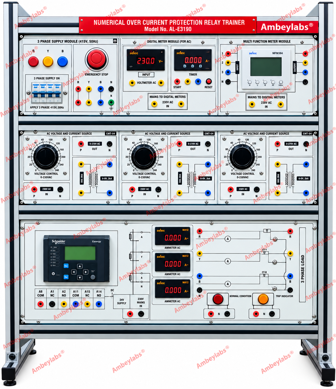
Project Information
- Category: ELECTRICAL ENGINEERING
- Sub Category: POWER SYSTEM AND PROTECTION LAB
- Model Number: AL-E319D
Description
AL-E319D NUMERICAL OVER CURRENT PROTECTION RELAY
TRAINER
AL-E319D
NUMERICAL OVER CURRENT PROTECTION RELAY TRAINER
AL-E319D
1.
Product Overview
The AL-E319D Numerical Over Current Relay
Protection Relay Trainer is a modular, rack-mounted training system
designed for practical study and experimentation on numerical protection relays
and three-phase power-system protection.
The trainer provides facilities for
studying DMT/IDMT under-current and over-current protection, earth-fault
protection and negative-sequence over-current protection. It incorporates a
three-phase power supply, current and potential transformer modules, digital
measurement modules, multifunction metering, a numerical protection relay,
tripping indication and a three-phase current-source arrangement.
2.
Scope of Learning / Experiments
The trainer shall provide facilities
for performing the following experiments:
1.
Study and
testing of DMT/IDMT under-current and over-current protection.
2.
Study and
testing of earth-fault protection.
3.
Study and
testing of negative-sequence over-current protection.
4.
Study of
numerical protection relay operation.
5.
Study of
relay tripping and indication.
6.
Study of
relay auto-reclose function.
7.
Study of
relay setting and communication with a PC.
8.
Study of RTU/SCADA
interfacing through the available communication interface.
3.
Detailed Technical Specifications
A. Power Supply
|
Parameter |
Specification |
|
Mains Supply |
415 V AC |
|
Frequency |
50 Hz |
|
Mains Tolerance |
+10% |
|
Supply Configuration |
Three-phase |
|
Protection |
MCB / short-circuit protection |
B.
Three-Phase Power Supply Module
The trainer shall incorporate a
dedicated Three-Phase Power Supply Module (415 V, 50 Hz).
Features
·
Three-phase
R-Y-B supply arrangement.
·
MCB
protection.
·
Emergency-stop
facility.
·
Individual
phase indication.
·
R-Y-B
indicator lamps.
·
Clearly
identified input/output terminals.
·
Safety
test points using appropriate safety sockets.
·
Suitable
isolation and protection for laboratory operation.
C.
Multifunction Meter Module
A digital multifunction meter shall be
provided for monitoring electrical parameters.
Measurement Parameters
·
Voltage
(V)
·
Current
(I)
·
Power
factor (PF)
·
Frequency
(Hz)
Power Factor Measurement
The specified measurement range shall
cover:
·
0.2 lag
·
Unity
·
0.2 lead
The multifunction meter shall be
mounted on the front panel for convenient observation during experiments.
D.
Digital AC Meter Module
A dedicated digital meter module shall
be provided for AC measurements.
Digital AC Voltmeter
·
Digital AC
voltage measurement.
·
Front-panel
display.
·
Clearly
identified input terminals.
Digital AC Ammeter
·
Digital AC
current measurement.
·
Front-panel
display.
·
Clearly
identified input terminals.
The digital meters shall permit
monitoring of the electrical quantities during protection experiments.
4.
Current Transformer Module
The trainer shall include a dedicated Current
Transformer (CT) Module.
Specification
·
Number of
CT units: 3 Nos.
·
Suitable
for three-phase current measurement and protection experiments.
·
CT
connections shall be brought to accessible front-panel terminals.
·
Terminals
shall be clearly marked for safe experimental connections.
The three CTs shall facilitate the
study of phase-current measurement and numerical over-current/earth-fault
protection.
5.
Potential Transformer Module
A dedicated Potential Transformer (PT)
Module shall be provided.
Specification
·
Number of
PT units: 3 Nos.
·
Three-phase
voltage sensing arrangement.
·
Accessible
front-panel terminals.
·
Suitable
for voltage measurement and protection-relay applications.
6.
Tripping Indication Module
The trainer shall incorporate a visual
tripping indication system.
Specification
·
Lamp
holder: 230 V
·
Quantity: 2
Nos.
·
Suitable
for indicating relay/protection operating conditions.
·
Clearly
identified on the front panel.
The indication system shall allow the
student to observe the operation/tripping status of the protection system.
7.
Numerical Protection Relay Module
The trainer shall incorporate a
numerical protection relay for protection experiments.
Protection Functions
The relay shall support:
·
Over-current
protection
·
Earth-fault
protection
Additional Relay Function
·
Auto-reclose
function
Communication Interface
The relay shall provide:
·
9-pin D
(Male) connector for
interface with RTU/SCADA automation.
·
Modbus RTU
RS-485 interface for RTU/SCADA
communication.
The relay shall be suitable for
practical study of numerical protection, relay settings, tripping and
automation interface.
8.
Three-Phase Current Source Module
A dedicated three-phase current-source
section shall be incorporated for protection-relay testing.
Specification
·
Three-phase
current-source arrangement.
·
Circuit
provided for OCR relay testing.
·
Suitable
for injecting/testing current conditions required for over-current protection
experiments.
·
Front-panel
connections for convenient experimental wiring.
9.
Protection and Safety Features
The trainer shall incorporate
appropriate laboratory protection provisions including:
·
MCB-based
short-circuit protection.
·
Emergency-stop
facility.
·
Clearly
identified phase terminals.
·
Safety
test points.
·
4 mm
safety sockets for high-voltage test points.
·
Properly
insulated front panel.
·
Modular
construction.
·
Clearly
printed electrical circuits and symbols.
·
Protected
internal wiring.
10.
Construction
The trainer shall be constructed as a modular
rack-type system.
Mechanical Construction
·
Modular
rack-type cabinet.
·
Aluminium
extruded metal construction.
·
Robust
laboratory-grade enclosure.
·
Front
panel with printed circuit diagrams and symbols.
·
Components
arranged for easy access and observation.
·
Suitable
for repeated educational laboratory use.
Approximate Dimensions
42" × 24"
11.
Front Panel
The front panel shall be professionally
laid out and shall include:
·
Three-phase
supply section.
·
MCB.
·
Emergency-stop
switch.
·
R-Y-B
indicators.
·
Digital AC
voltmeter.
·
Digital AC
ammeter.
·
Multifunction
meter.
·
CT
connections.
·
PT
connections.
·
Numerical
protection relay.
·
Tripping
indication lamps.
·
Three-phase
current-source connections.
·
Relay
communication interface.
·
Safety
terminals and patch points.
The electrical circuits and symbols
shall be clearly printed on the panel for easy understanding of the protection
scheme.
12.
Interconnection Accessories
The trainer shall be supplied with:
·
4 mm
heavy-duty patch cords
·
Patch-cord
length: 1 metre
·
Safety
sockets for high-voltage test points.
·
Necessary
interconnection provisions between the modules.
13.
PC / Relay Communication
The trainer shall support
computer-based relay communication.
Communication Accessories
·
RS232 port
for PC communication.
·
Relay-setting
software supplied on CD.
·
RS232-to-USB
converter for USB interface.
RTU / SCADA Interface
The relay shall provide:
·
9-pin D
(M) connector.
·
Modbus RTU
RS-485 interface.
·
Provision
for RTU/SCADA integration and automation studies.
14.
Salient Features
·
Numerical
over-current and earth-fault protection trainer.
·
DMT/IDMT
protection experimentation.
·
Under-current
and over-current protection study.
·
Earth-fault
protection study.
·
Negative-sequence
over-current protection study.
·
Numerical
relay with auto-reclose function.
·
Three CT
units.
·
Three PT
units.
·
Digital AC
voltage and current measurement.
·
Multifunction
electrical parameter meter.
·
Three-phase
current-source circuit for OCR testing.
·
MCB
short-circuit protection.
·
Emergency-stop
facility.
·
R-Y-B
phase indication.
·
4 mm
safety sockets.
·
Heavy-duty
4 mm patch cords.
·
RS232 PC
communication.
·
Modbus RTU
RS-485 interface.
·
RTU/SCADA
interfacing capability.
·
Modular
aluminium rack construction.
·
Printed
electrical circuits and symbols.
·
Approximate
size: 42" × 24".
15.
Packing List
The supplied system shall include:
1.
AL-E319D
Over Current Protection Relay Trainer
2.
Patch
cords
3.
3-Phase
Resistive Load Unit
4.
Filament
lamps – 2 Units
5.
Relay
communication accessories as specified.
AL-E277A
3-PHASE RESISTIVE LAMP LOAD
16. General Description
The AL-E277A 3-Phase Resistive Lamp
Load is an associated resistive-load unit intended for use with the
protection-relay trainer for practical loading and protection experiments.
17.
Technical Specifications
|
Parameter |
Specification |
|
Control Switches |
15 Nos. |
|
Current Control |
Individual phase/current control |
|
Current per Switch |
400 mA |
|
Internal Bulbs |
15 Nos. |
|
Current Meter |
Provided for load measurement –
optional |
|
Operating Voltage |
24 V AC |
|
Frequency |
50 Hz |
|
Supply |
Three-phase AC |
|
Protection |
4-Pole MCB |
|
Approx. Size |
18" × 24" |
|
Mobility |
Wheels provided |
18.
AL-E277A Control Arrangement
The load unit shall provide:
·
15 control
switches.
·
Individual
current control through the switches.
·
Each
switch controls approximately 400 mA current.
·
15 bulbs mounted inside the cabinet.
·
Three-phase
indication.
·
Front-panel
load connections.
·
Optional
current meter for load measurement.
19.
Construction & Safety Features
·
Front
panel constructed using high-class insulated Bakelite sheet.
·
Circuit
diagrams and symbols clearly printed.
·
4 mm
heavy-duty patch cords.
·
High-voltage
test points provided with 4 mm safety sockets.
·
Metal
cabinet construction.
·
Short-circuit
protection through 4-pole MCB.
·
Three-phase
indications using 25 mm multi-coloured indicators.
·
Wheels
provided for easy movement.
20.
Complete System Configuration
The proposed protection training system
therefore comprises:
|
Sr. No. |
Module / Equipment |
Quantity |
|
1 |
AL-E319D Numerical Over Current Protection
Trainer |
1 Set |
|
2 |
Three-Phase Power Supply Module |
Integrated |
|
3 |
Current Transformer Module |
3 CTs |
|
4 |
Potential Transformer Module |
3 PTs |
|
5 |
Multifunction Meter Module |
Integrated |
|
6 |
Digital AC Voltmeter Module |
Integrated |
|
7 |
Digital AC Ammeter Module |
Integrated |
|
8 |
Numerical Protection Relay |
Integrated |
|
9 |
Tripping Indication Lamps |
2 Nos. |
|
10 |
Three-Phase Current Source / OCR
Circuit |
Integrated |
|
11 |
Patch Cords |
Supplied |
|
12 |
3-Phase Resistive Lamp Load –
AL-E277A |
1 Set |
|
13 |
Filament Lamps |
2 Nos. |
|
14 |
RS232/USB Communication Accessories |
Supplied |
Note: The specifications above are structured from the specifications you
supplied. Where the source does not state an exact electrical rating, relay
model, CT/PT ratio, current-source range, accuracy, dimensions of individual
modules, or software version, those values have not been invented.