

AL-E491 PLC AUTOMATION AND DRIVE CONTROL SYSTEM TRAINER
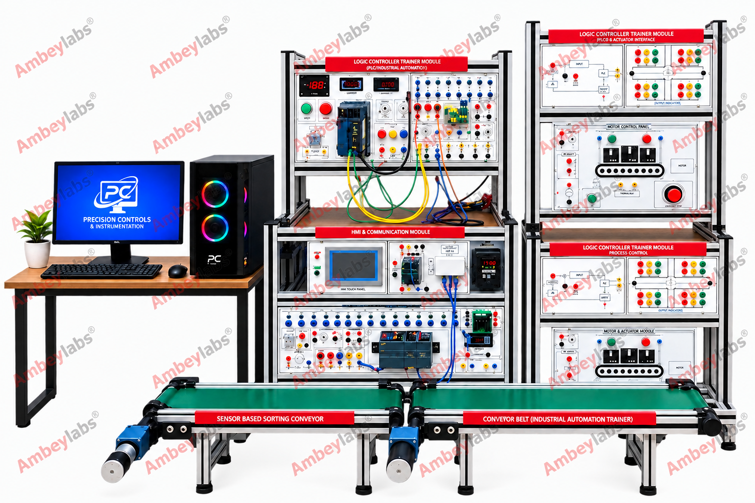
Project Information
- Category: ROBOTICS AND MECHATRONICS
- Sub Category: PLC TRAINER
- Model Number: AL-E491
Description
|
S.NO. |
ITEM SPECIFICATION |
|
1 |
The Training System Should have : PLC
with HMI Interface & classroom
Teaching Software Detailed Technical Specifications : |
|
PLC : |
|
|
CPU : 1212C (Siemens) |
|
|
Digital inputs : 8 nos.; Digital outputs
: 6 nos. |
|
|
Expansion Module : 8 Digital Inputs and
8 Digital Outputs |
|
|
Analog inputs : 2 nos. ; Resolution : 10
bit |
|
|
Input ranges (rated values), voltages :
(0 to +10 V) |
|
|
Memory : Work memory : 150 kbyte ; Load
memory : 4 Mbyte |
|
|
Analog output : 1 nos.; Resolution : 12
bit ; Communication : Ethernet/ PROFINET
|
|
|
Programming Software : TIA Portal
(Licensed) |
|
|
HMI Panel (Touch screen) |
|
|
HMI Supply : +24V DC |
|
|
CPU : 32-bits 400MHz RISC ; Interface :
Ethernet |
|
|
Display size : 7 inch ; Resolution : 800
× 480 TFT LCD 65, 536 colors |
|
|
Software : PI Studio |
|
|
General
Specifications : |
|
|
Toggle switches : 4 nos.; Push to ON
switches : 3 nos.; Proximity sensor : 1 no. |
|
|
Selector switch : 1 no.; Visual
indicators : 4 nos.; Audio indicator : 1 no.; DC motor : 1 no.; |
|
|
Relay card : 1 no. (Contains 2 relays)
;Voltage display : 1 no.; DC Contactor : 1 no. |
|
|
The Training System Should be capable to
perform the following Experiments : Experiments |
|
|
• Basic ladder logic programming using
TIA Portal. |
|
|
• Program operation • NO (normally open)
and NC (normally closed) instruction. • Types of logic gates. • Set and reset
bit. • Types of timers. • Types of counter. • Types of compare instruction. •
Types of math function. • Mov instruction. •NormX and SCALEX instructions. |
|
|
• Creating applications/screens in HMI. |
|
|
• Downloading and uploading programs. |
|
|
• Design screen for: |
|
|
• Switch and indicator in HMI for
communication with PLC. |
|
|
• Timer in HMI for communication with
PLC. |
|
|
• Counter in HMI for communication with
PLC. |
|
|
• Trend in HMI for communication with
PLC. |
|
|
• HMI screen development with buttons,
displays, graphs. |
|
|
• Sensor input simulation and actuator
output control. |
|
|
• Analog value scaling and display on
HMI. |
|
|
Classroom / Laboratory Teaching &
Learning Software Module on PLC and its Applications (Single User) : 1 No. |
|
|
• The trainer setup includes single user
license classroom / laboratory teaching, learning software module on PLC. The
content has easy explanation of various complex topics with animation and
simulation for ease of student learning. It also supports learning through
graphs, charts, along with mandatory rich content and theory to understand
fundamental concepts, interactive learning objects. |
|
|
• The learning module covers following topics: |
|
|
• Industrial Automation and tools like
PLC, SCADA, HMI, DCS. |
|
|
• Role of PLC in Automation |
|
|
• History of PLC |
|
|
• Types of PLC like Mini , Micro &
Rack |
|
|
• Block diagram of PLC |
|
|
• Working of PLC |
|
|
• Sinking and Sourcing Concept |
|
|
• PLC Program Cycle |
|
|
• Input Devices: |
|
|
• Switches, Introduction, Switch State,
Basic Switch Configuration, Toggle Switch, Slide Switch, Pushbutton, Rocker
Switch, DIP Switch, Reed Switch, Limit Switch. |
|
|
2 |
Application Modules to be interface with
PLC |
|
2.1 |
Application Module to study Temperature
Control by PLC . |
|
Temperature Control Module should be
able to perform the following Experiments |
|
|
• Study of temperature control. |
|
|
• Study and use of compare instruction. |
|
|
• Study and use of temperature sensors. |
|
|
• Study and use of controlling a heater
and fan. |
|
|
• Temperature control by PLC through
ladder program |
|
|
2.2 |
Traffic Light Control Module |
|
• Traffic Light Control Module should be
able to perform the following Experiments |
|
|
• Study of traffic light operation |
|
|
• Study and use of memory bit and
timers. |
|
|
• Traffic light control by PLC through
ladder program |
|
|
2.3 |
Application Module to study Conveyor
Belt control by PLC . |
|
Conveyor Belt Application Module should
be able to perform the following Experiments |
|
|
Study and use of: |
|
|
• Memory bit, timers, counters, compare
instruction |
|
|
• IR sensor, Proximity sensor, push to
on switch DC motor |
|
|
• Conveyor control by PLC through ladder
program |
|
|
• How to count metallic container using
a proximity switch? |
|
|
• How to run and control conveyor in
manual and AUTO mode using a PLC. |
|
|
3 |
AC Induction Motor Drive Training System
|
|
Technical Specification |
|
|
AC Drive (VFD) : Single phase 230vac, 0.75 HP
capacity , Supports IM / IPM /SPM motors and VF / SVC control, Built-in
keypad- Display: 7-segment or LCD for frequency, current, voltage.
Programmable motor parameters Overload & fault protection. |
|
|
Induction Motor :Single Induction motor- Power:
0.75HP, RPM: 2700, Class F insulation-
B3/B5 mounting |
|
|
Enclosure:
Epoxy-coated MS body with wiring diagram- Compact frame. |
|
|
Manual Control Panel : Push buttons (start/stop/Jog) and
speed potentiometer. |
|
|
List of Experiment Should be performed |
|
|
• Speed control of induction motor using
VFD. |
|
|
• Variable Frequency Drive (VFD) |
|
|
• Working principle of VFD. |
|
|
• Hardware connection of VFD. |
|
|
• Parameter setting of VFD. |
|
|
• Acceleration & deceleration time
setting in VFD. |
|
|
• Jog mode operation in VFD. |
|
|
• Direction control operation of motor. |
|
|
4 |
AC Servo Drive Training System |
|
Technical Specification |
|
|
AC Servo System : AC Servo Motor : 1 no.; Power : 400W ;
Rated Voltage : 220V |
|
|
Rated Speed : 0 to 3000 r/min. ; Current
: 1.0Ampere ; |
|
|
Control Type : PWM control using Drive |
|
|
Encoder: 2048 / 2500 / 10000 Pulse /
Rev. ( Incremental , Absolute) |
|
|
Servo Drive : 1 no. |
|
|
LED Display : 5 digit seven segment
display |
|
|
Function Key : 5 nos. (Mode , Shift ,
UP, Down , Set) |
|
|
Power :
400W ;Supply : 230VAC |
|
|
PLC : Digital input : 8nos ;
Digital output : 4nos |
|
|
Programming Software : ISP Soft
;Communication : USB Port |
|
|
Manual Control Panel : Switches (Start/Stop), Potentiometer , DC Voltage Display. |
|
|
Enclosure :
Epoxy-coated MS body with wiring diagram- Compact frame. |
|
|
List of Experiment Should be performed |
|
|
Suggested Experiments |
|
|
• Study and use of AC Servo motor and
drive |
|
|
• Study and use of AC Servo Drive
Function |
|
|
• Servo speed control using analog
voltage input using potentiometer . |
|
|
• Position control using pulse/direction
signal from PLC. |
|
|
• Study and use of AC Servo motor in Jog
mode. |
|
|
• Study and use of direction control of
Servo motor using PLC. |
|
|
• Position Control of AC Servo using
Drive and PLC |
|
|
We are committed to the continuous development of our
products, and therefore reserve the
right to amend specifications without prior notice |
|