

AL-E673A TRAFFIC LIGHT SIMULATOR USING PLC
Project Information
- Category: ROBOTICS AND MECHATRONICS
- Sub Category: PLC TRAINER
- Model Number: AL-E673A
Description
AL-E673A TRAFFIC
LIGHT SIMULATOR USING PLC
DETAILED
TECHNICAL SPECIFICATION
AL-E673A
TRAFFIC LIGHT SIMULATOR USING PLC
Product
Code: AL-E673A
Product Name: Traffic Light Simulator Using PLC
Category: PLC Trainers / Industrial Automation Training System
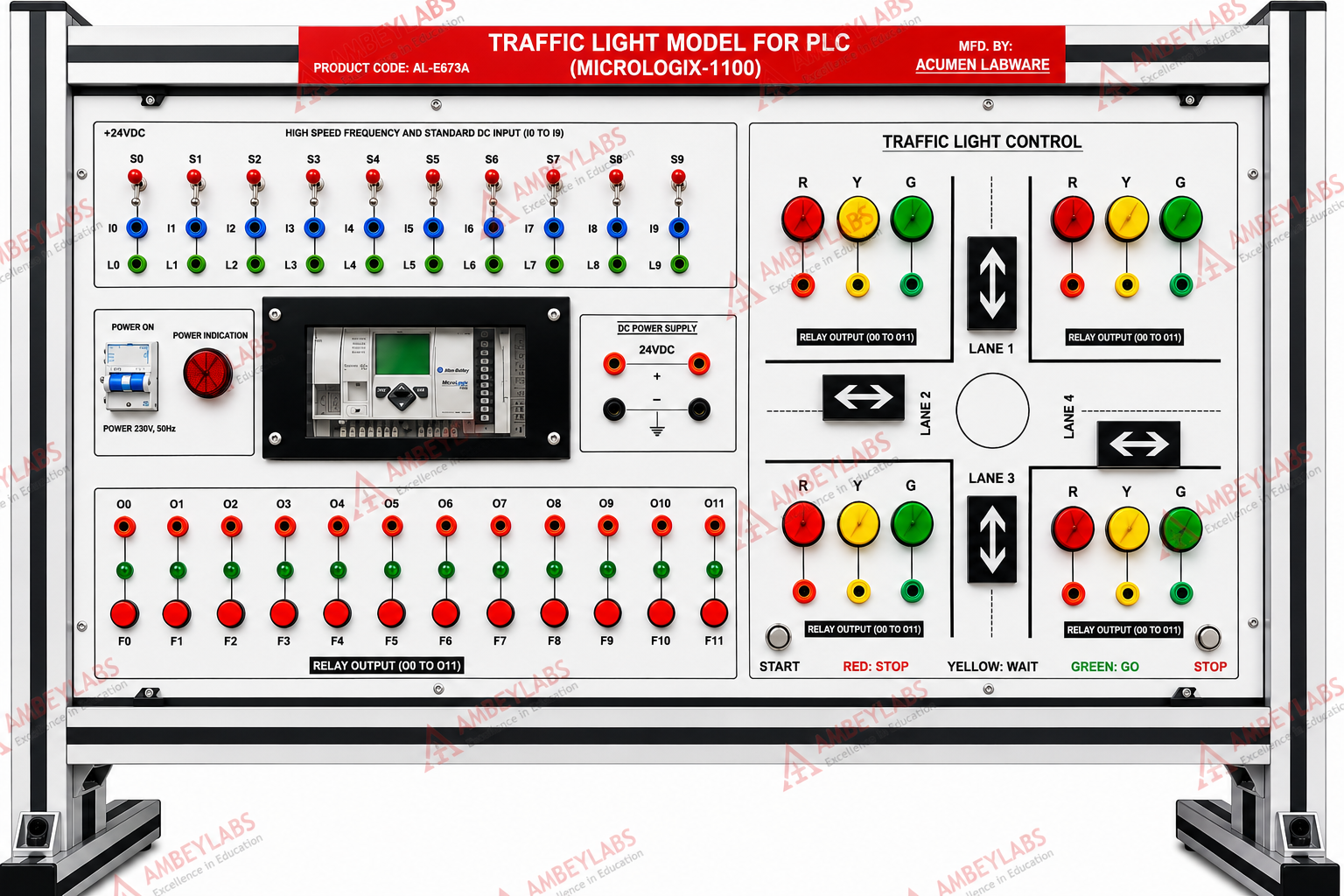
The AL-E673A Traffic Light Simulator Using PLC is a comprehensive
industrial automation trainer designed to demonstrate and study PLC-based
traffic signal control systems. The trainer enables students to design, develop,
test, and troubleshoot ladder logic programs for traffic light sequencing using
industrial PLC technology.
The system simulates a four-way traffic intersection with red, yellow,
and green signal indications, allowing learners to understand signal timing,
sequencing, timer operations, and traffic management logic. The trainer is
suitable for engineering colleges, polytechnic institutes, vocational training
centres, and industrial automation laboratories.
2. Educational
Objectives
The
trainer enables students to:
- Learn PLC programming fundamentals.
- Understand traffic light control logic.
- Develop ladder logic programs.
- Study timer-based sequential operations.
- Interface PLC inputs and outputs.
- Implement traffic signal sequencing.
- Study industrial automation techniques.
- Perform PLC troubleshooting and debugging.
3. Working
Principle
The
Traffic Light Simulator operates using a PLC programmed with ladder logic.
The PLC
continuously executes the programmed sequence to:
- Control red, yellow, and green signal lamps.
- Manage traffic flow at a four-way intersection.
- Control signal timing using PLC timers.
- Prevent conflicting traffic movements.
- Display traffic indications for each road.
- Repeat the programmed cycle automatically.
4.
Technical Specifications
PLC
Specifications
|
Parameter |
Specification |
|
PLC Platform |
Allen Bradley RS Logix 1100 |
|
Programming Software |
RS Logix |
|
Logic Voltage |
24 V DC |
|
I/O Rating |
24 V DC / 220 V AC |
|
Discrete Inputs |
10 |
|
Discrete Outputs |
12 |
|
High-Speed Inputs |
I0 to I7 |
|
Output Type |
Relay Output |
|
Maximum Relay Load |
2 A at 24 V DC / 220 V AC |
5. Power
Supply
|
Parameter |
Specification |
|
Input Supply |
230 V AC ±10%, 50 Hz |
|
DC Supply |
SMPS Based +24 V DC |
|
Current Rating |
2 A |
6. Input
Devices
The
trainer incorporates:
- 10 Digital Data Switches
- Manual PLC Input Simulation
- High-Speed Digital Inputs
- Industrial Input Interface
7. Output
Devices
The output
section includes:
- 12 LED Output Indicators
- 24 mm Industrial LED Signal Lamps
- Red Signal Indicators
- Yellow Signal Indicators
- Green Signal Indicators
- Aero Display for Side Indication
- PLC Output Status LEDs
8. Traffic
Signal Simulation
The
trainer simulates:
- Four-way Road Junction
- Red Signal (STOP)
- Yellow Signal (READY/WAIT)
- Green Signal (GO)
- Automatic Signal Sequencing
- Multi-Directional Traffic Control
- Side Signal Indication
9. PLC
Interface
The
trainer supports:
- Ladder Logic Programming
- Timer Instructions
- Digital Input Programming
- Digital Output Programming
- Relay Output Control
- Sequential Logic Development
- Industrial PLC Applications
10.
Control Panel Features
The front
panel includes:
- Power ON Indicator
- Digital Input Switches
- Output LED Indicators
- Red Signal Lamps
- Yellow Signal Lamps
- Green Signal Lamps
- Side Direction Indicators
- PLC Interface Connectors
- 4 mm Patch Cord Sockets
- Printed Circuit Symbols
11.
Construction
The
trainer is housed in a rugged ABS plastic cabinet with an insulated printed
circuit board front panel.
Construction
Features
- High-quality ABS Plastic Cabinet
- Industrial Printed Circuit Front Panel
- Screen-Printed Circuit Diagram
- Clearly Marked Symbols
- Laboratory-Grade Construction
- Compact Desktop Design
12. Safety
Features
- Short Circuit Protection by Fuse
- Low Voltage PLC Operation
- Industrial Relay Outputs
- Insulated PCB Front Panel
- Safety 4 mm Connection Sockets
- Protected Power Supply
13.
Practical Experiments
Students
can perform the following experiments:
- PLC Programming Fundamentals
- Ladder Logic Programming
- Traffic Light Sequencing
- Timer Programming
- Traffic Signal Automation
- Digital Input Programming
- Digital Output Programming
- Relay Output Control
- Sequential Control Systems
- Traffic Junction Management
- PLC Troubleshooting
- Industrial Automation Applications
14.
Learning Scope
The
trainer supports practical learning in:
- Traffic Light Simulation Using PLC
- Traffic Signal Operation
- Ladder Logic Programming
- PLC Timer Functions
- Traffic Light Control through PLC
- Red, Yellow, and Green Signal Logic
- Multi-Directional Traffic Control
15.
Dimensions
|
Parameter |
Specification |
|
Trainer Size |
Approximately 36 × 16 inches |
16. Scope
of Supply
- AL-E673A Traffic Light Simulator Using PLC
- Built-in PLC Interface
- 10 Digital Input Switches
- 12 LED Output Indicators
- Red, Yellow, and Green LED Signal Lamps
- Aero Display Indicators
- 4 mm Patch Cords
- User Instruction Manual
17.
Optional Accessories
- No optional
accessories specified.
18.
Applications
The
trainer is suitable for:
- PLC Programming Laboratory
- Industrial Automation Laboratory
- Electrical Engineering Laboratory
- Electronics Engineering Laboratory
- Mechatronics Laboratory
- Polytechnic Colleges
- Engineering Colleges
- Industrial Training Institutes (ITI)
- Vocational Training Centres
- Skill Development Centres
19.
Learning Outcomes
After
completing the practical exercises, students will be able to:
- Develop ladder logic programs for traffic signal control.
- Configure PLC digital inputs and relay outputs.
- Implement timer-based sequencing.
- Design traffic light control algorithms.
- Interface PLCs with external devices.
- Analyze and troubleshoot industrial PLC systems.
- Understand practical applications of PLC-based automation.
20.
Salient Features
- PLC-based traffic light simulator using Allen Bradley RS Logix
1100
- 10 digital inputs and 12 relay outputs
- 24 V DC PLC logic with 230 V AC mains operation
- High-speed input channels (I0–I7)
- Red, Yellow, and Green industrial LED signal lamps
- Four-way traffic junction simulation
- Ladder logic programming using RS Logix software
- Built-in SMPS power supply (+24 V DC, 2 A)
- 4 mm safety patch cord connections
- Fuse-protected outputs and insulated PCB front panel
- Compact ABS plastic cabinet with printed circuit layout
- Ideal for PLC, industrial automation, and traffic control training
laboratories.