

AL-E692A BLDC MOTOR CONTROL TRAINER USING PWM CONTROLLER
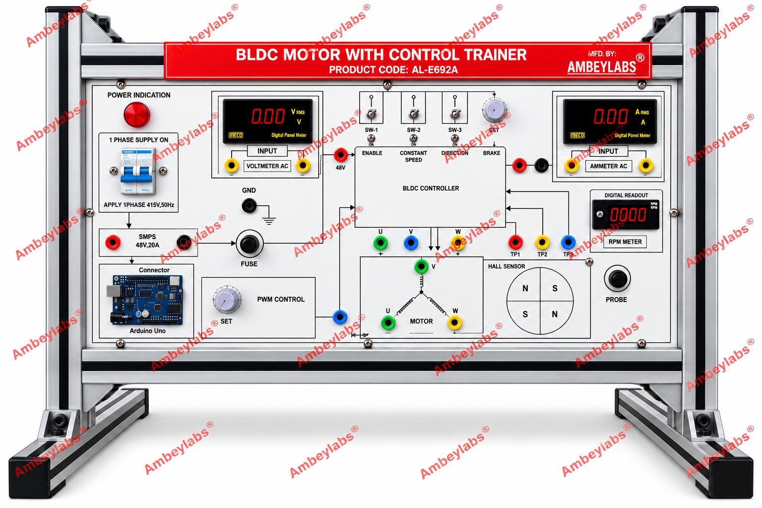
Project Information
- Category: ROBOTICS AND MECHATRONICS
- Sub Category: PLC TRAINER
- Model Number: AL-E692A
Description
AL-E692A BLDC MOTOR CONTROL TRAINER USING PWM CONTROLLER
BLDC Motor with Control Trainer — Model
AL-E692A
Manufacturer:
AMBEYLABS®
1. Product Description
The BLDC Motor with Control Trainer,
Model AL-E692A, is a laboratory training system designed to demonstrate the
operation, electronic commutation, speed regulation, direction control,
braking, and Hall sensor feedback of a Brushless DC (BLDC) motor. The trainer
is mounted on an aluminium profile frame and incorporates a BLDC controller,
PWM speed control, digital measuring instruments, an RPM display, a Hall sensor
arrangement, an Arduino Uno interface, and color-coded connection terminals.
2. Detailed Technical Specifications
|
S. No. |
Parameter |
Specification |
|
1 |
Product Name |
BLDC Motor with Control Trainer |
|
2 |
Model Number |
AL-E692A |
|
3 |
Manufacturer |
AMBEYLABS® |
|
4 |
Construction |
Aluminum profile-mounted trainer |
|
5 |
Input Supply |
1-phase AC, 415 V, 50 Hz, as
indicated on the panel |
|
6 |
DC Power Supply |
SMPS-based regulated supply |
|
7 |
SMPS Rating |
48 V DC, 20 A, as labeled |
|
8 |
Motor Type |
Brushless DC motor |
|
9 |
Motor Phase Terminals |
U, V and W |
|
10 |
Motor Controller |
Electronic BLDC controller |
|
11 |
PWM Control |
Adjustable PWM control knob |
|
12 |
Enable Control |
Dedicated enable switch |
|
13 |
Speed Control |
Constant-speed control switch |
|
14 |
Direction Control |
Dedicated direction control switch |
|
15 |
Braking Facility |
Brake control input |
|
16 |
Voltage Measurement |
Digital AC voltmeter |
|
17 |
Current Measurement |
Digital AC ammeter |
|
18 |
Speed Measurement |
Digital RPM meter |
|
19 |
Rotor Position Detection |
Hall sensor arrangement |
|
20 |
Test Points |
TP1, TP2 and TP3 |
|
21 |
DC Supply Connection |
Positive and negative terminals |
|
22 |
Grounding |
Dedicated GND terminal |
|
23 |
Protection |
Fuse provided on the panel |
|
24 |
Microcontroller Interface |
Arduino Uno board mounted on the
trainer |
|
25 |
Connection Terminals |
Color-coded banana terminals |
|
26 |
Indication |
Power ON indicator lamp |
|
27 |
Circuit Identification |
Clearly labelled functional blocks
and connection diagram |
|
28 |
Mounting |
Rigid laboratory frame with
supporting feet |
3. Functional Sections
- Power supply section: SMPS rated 48 V
DC, 20 A, as marked on the panel.
- BLDC controller section: Electronic
motor control with enable, constant-speed, direction and brake controls.
- PWM control section: Rotary adjustment
for studying PWM-based motor speed regulation.
- Digital measurement section: Digital
AC voltage and current meters for electrical measurements.
- RPM measurement section: Digital
display for monitoring motor rotational speed.
- Hall sensor section: Demonstration of
rotor-position sensing and its role in electronic commutation.
- Motor connection section: Three-phase
terminals U, V and W.
- Microcontroller section: Arduino Uno
board for supported microcontroller-based experiments.
- Test-point section: TP1, TP2 and TP3
for observing designated controller signals.
- Safety and grounding section: Fuse,
grounding terminal and identified supply connections.
Major
Functional Sections
A. DC Power Supply Section
- Provides the DC supply for operating
the BLDC controller. The panel identifies a 48 V, 20 A SMPS, together with
supply terminals and fuse protection.
B. BLDC Motor Controller Section
- Provides electronic motor control and
switching functions, with panel controls for enable, constant speed,
direction and braking. The motor phase terminals are identified as U, V
and W.
C. PWM Speed Control Section
- Allows the user to vary the PWM
command through a rotary adjustment knob and investigate its effect on
motor speed and operation.
D. Digital Measurement Section
- Includes digital voltage and current
displays for electrical measurements. The displayed values and measurement
ranges depend on the installed meter configuration.
E. Hall Sensor and RPM Measurement Section
- Supports the study of rotor-position
sensing and electronic commutation. A digital RPM meter is provided for
observing motor speed, while TP1, TP2 and TP3 allow access to designated
test signals.
F. Microcontroller Interface
- An Arduino Uno board is shown on the
trainer. It can support microcontroller-related experiments, subject to
the actual circuit connections and controller interface provided by the
manufacturer.
4. Scope of Learning and Experiments
- Study of BLDC motor construction and
operating principles.
- Study of electronic commutation in
BLDC motors.
- Identification of three-phase motor
terminals.
- Study of Hall effect sensors and
rotor-position detection.
- Study of PWM-based speed control.
- Investigation of the relationship
between PWM command and motor speed.
- Study of motor enable and disable
functions.
- Study of motor direction control.
- Investigation of braking control.
- Measurement of motor speed using a
digital RPM meter.
- Observation of voltage and current
during motor operation.
- Study of BLDC controller test points.
- Introduction to microcontroller-based
motor control.
- Study of motor starting, stopping and
speed variation.
5. Standard Features
- Aluminum profile construction.
- Integrated BLDC motor control panel.
- Adjustable PWM control.
- Digital AC voltmeter and ammeter.
- Digital RPM display.
- Hall sensor demonstration section.
- Dedicated motor phase terminals.
- Arduino Uno interface.
- Color-coded connection terminals.
- Fuse and grounding provision.
- Clearly labeled switches and controls.
- Suitable for supervised laboratory
training.
6. Applications
- Electrical machines laboratories.
- Power electronics laboratories.
- Electric vehicle technology
laboratories.
- Mechatronics and automation training.
- Motor control and drive experiments.
- Diploma and undergraduate engineering
education.
- Technical and vocational training centers.
7. Recommended Supply Items
The complete supply should include the
trainer, compatible BLDC motor, required connecting leads, operating manual,
circuit diagrams, experiment manual, and relevant microcontroller program files
where applicable.
8. Important Technical Verification
- The panel specifies 1-phase AC, 415 V,
50 Hz. This is an unusual rating for a single-phase laboratory supply;
confirm the correct input voltage with the manufacturer before connecting
the equipment to mains.
- The 48 V DC, 20 A supply has a nominal
output capacity of 960 W. This does not establish the motor's rated power.
- Motor wattage, rated RPM, controller
ratings, meter accuracy and PWM frequency are not specified on the visible
panel and should be confirmed separately.
9. Tender Specification
BLDC Motor with Control Trainer, Model
AL-E692A: The system shall be mounted on a rigid aluminum profile frame and
designed for studying BLDC motor operation, electronic commutation, Hall sensor
feedback, PWM speed regulation, direction control and braking. It shall
incorporate a BLDC controller, 48 V DC SMPS rated 20 A as indicated on the
panel, digital AC voltmeter and ammeter, digital RPM meter, Hall sensor
arrangement, PWM control knob, enable/speed/direction/brake controls, U-V-W
motor terminals, test points TP1–TP3, fuse, grounding terminal, Arduino Uno
interface and color-coded connection facilities. The trainer shall be supplied
with suitable accessories, operating instructions, circuit diagrams and an
experiment manual.
OPTIONAL
ACCESSORIES:
· No