

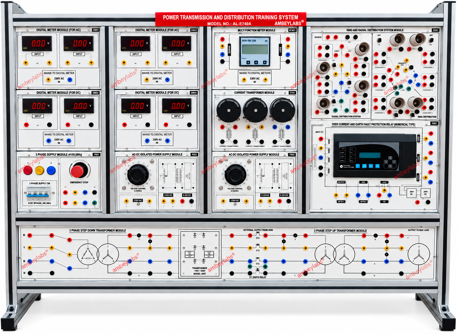
AL-E740A POWER TRANSMISSION AND DISTRIBUTION TRAINING SYSTEM
Project Information
- Category: ELECTRICAL ENGINEERING
- Sub Category: ELECTRICAL ENGINEERING
- Model Number: AL-E740A
Description
AL-E740A POWER
TRANSMISSION AND DISTRIBUTION TRAINING SYSTEM
1. Product Overview
The AL-E740A
Power Transmission and Distribution Training System is a modular
educational training platform designed for practical study of power
transmission, distribution, transformer operation, protection, metering,
transmission-line characteristics, and electrical faults.
The system
provides practical facilities for studying no-load and load characteristics of
transmission lines, Ferranti effect, efficiency, voltage regulation, power
flow, symmetrical and asymmetrical faults, three-phase transformer distribution
systems, over-current protection and earth-fault protection.
2. Scope of Learning
The
training system shall facilitate the following experiments and studies:
- Study of no-load test
and Ferranti effect on a transmission line.
- Load test and
calculation of efficiency, regulation and power flow using the π-model
of a transmission line.
- Load test and
calculation of efficiency, regulation and power flow using the short
transmission-line model.
- Study of symmetrical
faults on a transmission line.
- Study of asymmetrical
faults on a transmission line.
- Study of a three-phase
transformer distribution system.
- Study of over-current
and earth-fault protection systems.
3. Main Power Supply
- AC output supply: 0–415
V, 6 A
- Input mains: 415 V
AC, 50 Hz +10%
4. EMT-01 – Three-Phase Power
Supply Module
The
three-phase power supply module shall include:
- Four-pole MCB rated 415
V, 16 A.
- Three-phase power
indication using R-Y-B indicators.
- Built-in contactor:
ü Coil voltage: 230 V
ü Frequency: 50 Hz
ü Coil consumption: 11 VA
- Emergency-stop
facility for emergency conditions.
5. EMT-04 – Multifunction Meter
Module
The
multifunction meter shall provide bidirectional electrical measurement and
monitoring.
Technical
Specifications
- Meter type: Bidirectional
multifunction meter
- System: 3-phase,
3/4-wire
- Rated voltage: 415
VAC
- CT input: 5 A
- Display: LCD/LED
- Auxiliary supply: 230
V
- Auxiliary frequency: 45–65
Hz
- Power consumption: 5
W
- Measurements:
ü Voltage (V)
ü Current (I)
ü Frequency (Hz)
ü Power factor (PF)
ü Apparent power (kVA)
ü Active power (kW)
ü Energy (kWh)
- Communication: Modbus
RTU RS-485
- RTU/SCADA interface:
Optional
- Provision for
operation from 230 V AC
- R-Y-B-N output
distribution points provided.
6. EMT-02 – Digital AC Meter
Module
Quantity:
2 Nos.
Each module
shall provide:
- Digital AC voltmeter:
- Range: 0–300 V AC
- Quantity: 1 No.
- Digital AC ammeter:
- Range: 0–10 A AC
- Quantity: 1 No.
7. EMT-03 – Digital DC Meter
Module
Quantity:
2 Nos.
Each
module shall provide:
- Digital DC voltmeter:
- Range: 0–300 V DC
- Quantity: 1 No.
- Digital DC ammeter:
- Range: 0–10 A DC
- Quantity: 1 No.
8. EMT-48 – Current Transformer
Module
The
module shall contain:
- Current transformers: 3
Nos.
- CT ratio: 20:1
9. EMT-62 – AC/DC Isolated Power
Supply Module
Quantity:
2 Nos.
The
module shall incorporate:
- Auto-transformer:
- Current rating: 2
A
- Application: voltage
control
- Isolated transformer:
- Output: 0–230 V /
2 A
- Suitable for AC/DC
applications.
10. EMT-68 – Ring and Radial
Distribution Module
The
distribution module shall include:
- Switching arrangement.
- Lamp holders: 8
Nos.
- 4 mm sockets.
- Facilities for
practical study of ring and radial distribution arrangements.
11. EMT-67 – Numerical
Over-Current and Earth-Fault Protection Relay
The
numerical protection relay shall provide:
- Over-current
protection.
- Earth-fault
protection.
- Auto-reclose function.
- 9-pin D-type male
connector for RTU/SCADA
automation interface.
- Modbus RTU RS-485 communication
interface.
12. Main Circuit / Distribution
Panel Module
The
main distribution panel shall provide:
- Three-phase input
connection from 415 V mains / auto-transformer.
- Provision for
connecting a three-phase step-down transformer.
- Provision for
connecting a three-phase step-up transformer.
- Built-in small
transmission-line section.
- Provision for
connection of 3 CTs.
- One CT provided
inbuilt.
- End-load distribution
system.
- Front-panel circuit
representation with clearly printed electrical symbols and circuits.
13. General Construction and
Safety Features
The
complete trainer shall include:
- High-quality insulated
front panel.
- Clearly printed
electrical circuits and symbols.
- Instruction manual.
- Heavy-duty 4 mm
patch cords, approximately 1 metre length.
- High-voltage test
points using 4 mm safety sockets.
- Modular rack-type
construction.
- Aluminium extruded
metal cabinet.
- Short-circuit
protection through MCB.
- Approximate overall
trainer size: 54 × 24 inches.
14. Packing List
The
complete system shall include:
- AL-E740A Transmission
and Distribution Protection Trainer
- Patch cords of
different lengths.
- AL-E277 Three-Phase
Resistive Load
- Filament lamps – 8
units
- AL-E920 Transmission
Line Model
- AL-E295A Three-Phase
Transformer – Step Down
- AL-E295B Three-Phase
Transformer – Step Up
- AL-E295A Three-Phase
Transformer – Step Down as listed in the source packing list.
- AL-E302 Three-Phase
Auto Transformer
- RS-485 patch cable:
ü 6-pin mini-DIN male to
6-pin mini-DIN male
ü Length up to 1.5 m
ü Quantity: 1 No.
15. AL-E277 – Three-Phase
Resistive Load, 3kW
Technical
Specifications
- Rated load: 3kW
- Three control switches
provided for individual phase current control.
- Each switch controls
approximately 1 A current.
- Rheostats: 9 Nos.
- Rheostat current
rating: 1 A
- Rheostat resistance: 440
Ω
- Rated condition: 1
A at 415 V
- Current meter provided
for load measurement.
- Operating supply: 415
V, 50 Hz AC, three-phase.
Construction
and Safety
- Insulated Bakelite
front panel.
- Printed circuit
diagrams and symbols.
- Instruction manual.
- Three-phase indication
using 25 mm multi-coloured indicators.
- Heavy-duty 4 mm patch
cords.
- 4 mm safety sockets
for high-voltage test points.
- Metal cabinet.
- Four-pole MCB for
short-circuit protection.
- Approximate size: 18
× 24 inches.
- Wheels provided for
easy movement.
16. AL-E920 – Three-Phase
Transmission Line Module
Scope of
Learning
The
module shall support:
- No-load
transmission-line testing.
- Ferranti-effect study.
- Load testing.
- Efficiency
calculation.
- Voltage-regulation
calculation.
- Power-flow
measurement.
- π-model
transmission-line studies.
- Short-model
transmission-line studies.
- Symmetrical fault
studies.
- Asymmetrical fault
studies.
Transmission-Line
Simulation Components
The
simulation model shall be constructed using:
- Resistors:
ü 5 Ω
ü 600 W
- Inductor:
ü 80 mH
ü 5 A
- Capacitor:
ü 0.47 µF
ü 600 V
Line
Simulation
The
model shall simulate:
- Medium/long
transmission lines of approximately 125 km / 250 km using the
π-model.
- Medium/long
transmission lines of approximately 125 km / 250 km using the
T-model.
Construction
- Fan-cooled tabletop
arrangement.
- Designed for long operating
life.
- Insulated Bakelite
front panel.
- Printed circuit
diagrams and symbols.
- 4 mm safety sockets
for high-voltage test points.
- Heavy-duty 4 mm patch
cords, approximately 1 m.
- Modular panel
construction.
- Wheels for easy
positioning.
- Removable covers.
- Approximate size: 30
× 16 inches.
17. AL-E295 – Three-Phase
Transformer, Step Down
Scope
- Practical study of a
three-phase transformer.
- Step-down transformer
operation.
Technical
Specifications
- AC supply: 440/220
V
- Capacity: 1.5 KVA
- Input mains: 415 V,
50 Hz +10%
- Rating: 1.5 KVA per
phase
- Transformer ratio: 2:1
step-down
- 440 V tapping
positions:
ü 0%
ü 0%
ü 86.6%
ü 100%
- High-insulation copper
winding.
- Transformer ratings
available from 1–10 kVA.
Construction
and Safety
- Insulated Bakelite
front panel.
- Printed circuit
representation.
- Instruction manual.
- High-voltage test
points with 4 mm safety sockets / BTI-15 terminals.
- Metal cabinet.
- Fuse-based
short-circuit protection.
- Approximate size: 18
× 12 inches.
18. AL-E295 –
Three-Phase Transformer, Step Up
Scope
- Practical study of
three-phase transformer operation.
- Step-up transformer
operation.
Technical
Specifications
- AC supply: 220/440
V
- Capacity: 1.5 KVA
- Input mains: 415 V,
50 Hz +10%
- Rating: 1.5 KVA per
phase
- The source document
specifies a transformer ratio of 2:1 and labels this unit as Step
Up.
- 440 V tapping
positions:
ü 0%
ü 0%
ü 86.6%
ü 100%
- High-insulation copper
winding.
- Transformer ratings
available from 1–10 kVA.
Construction
and Safety
- Insulated Bakelite
front panel.
- Printed circuit
diagrams.
- Instruction manual.
- 4 mm safety sockets /
BTI-15 high-voltage terminals.
- Metal cabinet.
- Fuse-based
short-circuit protection.
- Approximate size: 18
× 12 inches.
19. AL-E302 –
Three-Phase Auto Transformer
- Practical study and
operation of a three-phase Variac / auto-transformer.
Technical
Specifications
- AC output: 0–415 V
- Current rating: 4 A
- Input mains: 415 V,
50 Hz +10%
- Copper-wound
auto-transformer.
Construction
and Safety
- Insulated Bakelite
front panel.
- Printed circuit
diagrams and symbols.
- Instruction manual.
- High-voltage test
points with 4 mm safety sockets / BTI-15 terminals.
- Metal cabinet.
- Fuse-based
short-circuit protection.
- Wheels for easy
movement.
- Approximate weight: 25
kg
- Approximate
dimensions: 20 × 12 inches.
20.
Catalogue Presentation
The
complete system is intended as a modular laboratory setup combining:
415 V
Three-Phase Supply → Metering → CT Measurement → Transmission-Line Model →
Transformer Step-Up/Step-Down → Distribution Network → Resistive Load →
Numerical Protection Relay
The
supplied source identifies the system as AL-E740A Power Transmission and
Distribution Training System and specifies the complete modular rack
construction and associated equipment.