

AL-E767A SINGLE AND THREE PHASE INVERTER/ CHOPPER 1.5KW
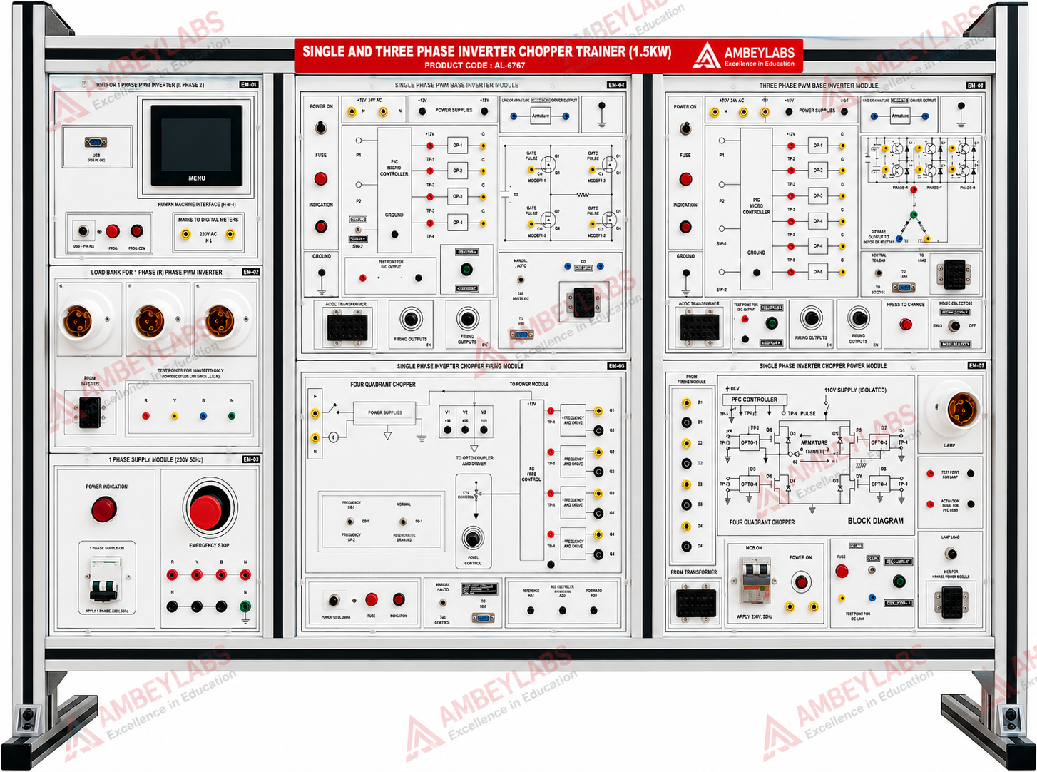
Project Information
- Category: ELECTRICAL ENGINEERING
- Sub Category: POWER ELECTRONICS AND DRIVE LAB
- Model Number: AL-E767A
Description
AL-E767A SINGLE AND THREE PHASE INVERTER/ CHOPPER 1.5KW
AL-E767A SINGLE & THREE PHASE INVERTER AND
CHOPPER TRAINER (1.5 kW)
Product Code: AL-E767A
Product Name: Single & Three Phase Inverter and Chopper Trainer (1.5 kW)
Category: Power Electronics Laboratory Trainer / Electrical Engineering Trainer
Prepared
from the uploaded technical document.
1. Product Overview
The AL-E767A Single &
Three Phase Inverter and Chopper Trainer is an advanced power electronics
laboratory trainer designed to study the operation, characteristics, and
control of PWM Inverters and DC Choppers. The trainer provides a comprehensive
platform for practical experiments on single-phase and three-phase inverter
circuits along with 1-, 2-, and 4-quadrant DC chopper configurations.
The system incorporates a
high-power MOSFET-based inverter module, PWM generation using the triangular
comparator method, built-in HMI, lamp load assembly, PMDC motor load,
protection circuits, and modular interconnections, making it ideal for
engineering colleges, polytechnic institutes, vocational training centres, and
industrial training laboratories.
2. Educational Objectives
The trainer enables students to:
- Study PWM inverter operation.
- Understand single-phase inverter
circuits.
- Study three-phase inverter circuits.
- Analyze DC chopper operation.
- Perform experiments on 1-, 2-, and
4-quadrant choppers.
- Understand PWM generation techniques.
- Study MOSFET-based power converters.
- Analyze switching waveforms.
- Perform practical measurements and
troubleshooting.
3. Scope of Learning
The trainer supports practical experiments on:
- Single Phase PWM Inverter
- Three Phase PWM Inverter
- Single Phase Chopper
- One Quadrant Chopper
- Two Quadrant Chopper
- Four Quadrant Chopper
4. Technical Specifications
Power Section
|
Parameter |
Specification |
|
Rated Power |
1.5 kW |
|
Input Supply |
110–220 V AC, 50/60 Hz |
|
Transformer |
Centre-Tapped 0–230 V
±10% |
|
Power Switch |
Single Phase 10 A MCB |
MOSFET Power Module
- MOSFET Rating: 1200 V / 25 A
- High-Speed Switching
- Modular Construction
- Easily Replaceable Module
PWM Generator
- PWM Technique: Triangular Comparator
Method
- Frequency Range: Approximately 270 Hz to
5 kHz
- Duty Cycle Adjustment:
- 0–90%
- 0–50%
Interconnection
- 2 mm Safety Sockets
- 4 mm Safety Sockets
- Colour-Coded Patch Cord Connections
5. Power Supply
The trainer incorporates:
- Built-in Single Phase AC Power Supply
- Centre-Tapped Transformer
- Power Distribution Circuit
- Protected MCB Input
- Internal Power Modules
6. Firing Circuits
The trainer provides dedicated firing circuits for:
- Single Phase Inverter
- Three Phase Inverter
- DC Chopper
7. Human Machine Interface (HMI)
- Built-in 3.5-inch HMI
- User-Friendly Operation
- System Monitoring
- Control Interface
8. Load Assembly
The trainer includes:
- Three 200 W Lamp Loads
- PMDC Motor Load (½ HP, 230 V)
- Power Output Terminals
- Load Connection Interface
9. Control Panel Features
The front panel incorporates:
- Main Power Switch
- Power ON Indicator
- Emergency Stop Push Button
- PWM Control Circuit
- Test Points
- Power Module Interface
- Lamp Load Connections
- Patch Cord Connections
- HMI Display
- Safety Terminals
10. Test Facilities
The trainer provides:
- Test Points for PWM Circuit
- Firing Pulse Monitoring
- Waveform Observation
- Modular Testing
- Practical Measurement Facilities
11. Protection Features
The trainer incorporates:
- Single Phase 10 A MCB Protection
- Three MCBs for Input AC Supply
- Short Circuit Protection
- Internal RC Snubber Circuit
- Emergency Stop Switch
- Protected MOSFET Power Module
- Fuse Protection
12. Construction
- Heavy-Duty Metal Cabinet
- Printed Bakelite/Aluminium Front Panel
- Industrial Screen-Printed Circuit Symbols
- Laboratory-Grade Construction
- Modular Replaceable Boards
- Rugged Industrial Design
13. Practical Experiments
Students can perform experiments on:
- Single Phase PWM Inverter
- Three Phase PWM Inverter
- PWM Generation
- MOSFET Switching Characteristics
- Chopper Circuit Operation
- One Quadrant Chopper
- Two Quadrant Chopper
- Four Quadrant Chopper
- Lamp Load Analysis
- PMDC Motor Speed Control
- Switching Waveform Analysis
- Frequency Variation
- Duty Cycle Variation
- Practical Troubleshooting
14. Safety Features
- Emergency Stop Facility
- MCB Protection
- Short Circuit Protection
- RC Snubber Protection
- Colour-Coded Safety Sockets
- Fully Insulated Front Panel
- Low-Risk Laboratory Connections
15. Mechanical Specifications
|
Parameter |
Specification |
|
Cabinet Type |
Metal Cabinet |
|
Front Panel |
Printed Circuit Board /
Aluminium |
|
Trainer Size |
48 × 24 inches |
16. Standard Accessories
The trainer is supplied with:
- Single & Three Phase Inverter and
Chopper Trainer
- Power Pack
- 2 mm Patch Cords
- 4 mm Patch Cords
- Instruction Manual
- Software/Instruction CD
- ½ HP, 230 V PMDC Motor
- Three 200 W Lamps
17. Applications
The trainer is suitable for:
- Power Electronics Laboratory
- Electrical Engineering Laboratory
- Electronics Engineering Laboratory
- Industrial Automation Laboratory
- Polytechnic Colleges
- Engineering Colleges
- Vocational Training Institutes
- Skill Development Centres
- Industrial Training Centres
18. Learning Outcomes
After completing the practical exercises, students
will be able to:
- Understand PWM inverter principles.
- Analyze single-phase and three-phase
inverter circuits.
- Design and test chopper circuits.
- Generate PWM firing pulses.
- Interface power electronic devices
safely.
- Measure switching characteristics.
- Analyze inverter output waveforms.
- Perform fault diagnosis and
troubleshooting.
- Apply power electronics concepts in
industrial applications.
19. Salient Features
- 1.5 kW inverter and chopper trainer
- Single-phase and three-phase PWM inverter
experiments
- 1-, 2-, and 4-quadrant chopper operation
- 1200 V / 25 A MOSFET power module
- PWM generation using triangular comparator
method
- Adjustable PWM frequency (270 Hz to 5
kHz)
- Built-in 3.5-inch HMI
- Integrated single-phase power supply
- Centre-tapped transformer (0–230 V ±10%)
- Three 200 W lamp loads and ½ HP PMDC
motor
- Emergency stop, MCB protection, RC
snubber, and short-circuit protection
- Modular, laboratory-grade metal cabinet
with safety sockets and printed front panel
- Ideal for power electronics, electrical
engineering, and industrial automation laboratories.